


7
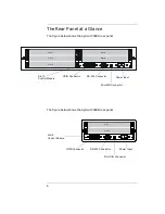
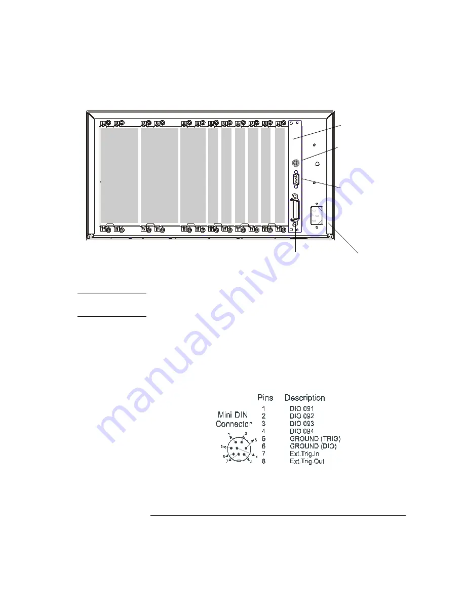
The figure below shows the Agilent 3499C rear panel.
Option FP1 (1-slot) and FP2 (2-slot) filler panels can be ordered to cover
any unused slots.
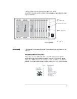
WARNING
For protection from electrical shock, the power cord ground must not be
defeated.
The Mini DIN Connector
The rear panel mini DIN connector is used to make connections to
external triggers and the built-in digital I/O port. An Agilent N2289A
cable (mini DIN to D9) can be ordered to assist connections to external
devices. The figure below shows the pins used in the mini DIN connector.
GPIB Connector
RS-232 Connector
Mini DIN Connector
Power Input
Sl
ot
1
Sl
ot
2
Sl
ot
3
Sl
ot
4
Sl
ot
5
Sl
ot
6
Sl
ot
7
(2
sl
ot
wi
dt
h)
Sl
ot
8
(3
sl
ot
w
idt
h)
Sl
ot
9
(3
sl
ot
wi
dt
h)
Slot 0
Control Module
Содержание Agilent 3499A
Страница 13: ...1 1 Quick Start ...
Страница 27: ...2 2 Front Panel Operation ...
Страница 55: ...3 3 System Overview ...
Страница 77: ...4 4 Features and Functions ...
Страница 113: ...5 5 Remote Interface Reference ...
Страница 164: ...164 5 ...
Страница 165: ...6 6 Error Messages ...
Страница 173: ...7 7 Plug in Modules ...
Страница 256: ...256 Chapter 7 Plug in Modules 44475A Breadboard Module 7 ...
Страница 261: ...261 Chapter 7 Plug in Modules 44476B Microwave Switch Module 4 7 The 44476B is shown below ...
Страница 268: ...268 Chapter 7 Plug in Modules 44478A B 1 3 GHz Dual 4 to 1 MUX Modules 7 The 44478A B is shown below ...
Страница 286: ...286 Chapter 7 Plug in Modules Terminals and Connections Information 7 ...
Страница 288: ...288 7 ...
Страница 289: ...8 8 Application Programs ...
Страница 299: ...9 9 Specifications ...
Страница 343: ...343 Chapter 9 Specifications 44475A Breadboard Module 4 9 ...


