102
Chapter 4 Features and Functions
Digital I/O Operation
4
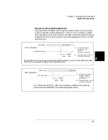
Full Handshake Mode #5
Handshake Mode #5 provides a complete two wire handshake with a
data direction line. During write operations, the PCTL line indicates that
output data is valid; during read operations, it indicates that the digital
I/O module (i.e. N2263A) is “ready for data”. The PFLG line is used by
the peripheral device to indicate “ready for data” during write operations
or “data valid” for read operations.
For this discussion, write operations mean the plug-in digital I/O module
is controlling the data lines. Read operations mean external devices
control the data lines and the digital I/O module reads the data and
controls the PCTL/RD line.
DATA VALID
DATA LINES
I/O DIRECTION
t 1 = T im e fr om I/O lin e
low to ch eck for
W rite O p e ra tion
P F L G low
t2 = T im e fro m P F L G
lo w to d a ta v a lid
(4 0
µ
s m in im u m )
t3 = T im e from d a ta v a lid
to P C T L lo w
PCTL LINE
PFLG LINE
t1
1 ms
t2
40
µ
s
t3
30
µ
s
t4
40
µ
s
t5
35
µ
s
(3 0
µ
s m in im u m )
t4 = T im e from P C T L lo w
to c h e ck for P F L G
h ig h (4 0
µ
s m in im u m )
t5 = T im e from P F L G
to P C T L h igh
(3 5
µ
s m in im u m )
(1 ms minimum)
The complete handshaking sequence for Mode #5 is as follows: The 3499A/B/C checks
to see if the receiving device has set the PFLG line low, this indicates the receiving
device is ready to accept data. When PFLG is low, the 3499A/B/C sets the data on the
data bus and sets PCTL low. The 3499A/B/C then waits for the receiving device to set
PFLG high, indicating that it has latched the data. To complete the handshake, the
3499A/B/C sets PCTL high.
Содержание Agilent 3499A
Страница 13: ...1 1 Quick Start ...
Страница 27: ...2 2 Front Panel Operation ...
Страница 55: ...3 3 System Overview ...
Страница 77: ...4 4 Features and Functions ...
Страница 113: ...5 5 Remote Interface Reference ...
Страница 164: ...164 5 ...
Страница 165: ...6 6 Error Messages ...
Страница 173: ...7 7 Plug in Modules ...
Страница 256: ...256 Chapter 7 Plug in Modules 44475A Breadboard Module 7 ...
Страница 261: ...261 Chapter 7 Plug in Modules 44476B Microwave Switch Module 4 7 The 44476B is shown below ...
Страница 268: ...268 Chapter 7 Plug in Modules 44478A B 1 3 GHz Dual 4 to 1 MUX Modules 7 The 44478A B is shown below ...
Страница 286: ...286 Chapter 7 Plug in Modules Terminals and Connections Information 7 ...
Страница 288: ...288 7 ...
Страница 289: ...8 8 Application Programs ...
Страница 299: ...9 9 Specifications ...
Страница 343: ...343 Chapter 9 Specifications 44475A Breadboard Module 4 9 ...

