136
Chapter 5 Remote Interface Reference
Scanning Commands
5
TRIGger
:TIMer <seconds>|MIN|MAX
:TIMer? [MIN|MAX]
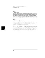
This command sets the channel-to-channel interval in the trigger layer
(the
ARM:TIMer
command sets the sweep-to-sweep interval in the
trigger layer). This timer is valid only if the
TIMer
is set using the
TRIGger:SOURce
command.
You can set seconds to any value between 0.000 (
MIN
) and 99999.999
(
MAX
) in increments of 0.001 seconds. When power is applied, the value is
set to 0 (
MIN
).
The
TRIGger:TIMer?
query returns the channel-to-channel interval in
seconds. The returned number is a value between 0 and 99999.999
(seconds). The optional parameters
MIN
and
MAX
allow you to query the
module for these values instead of looking them up in the command
reference.
MIN
returns “0” and
MAX
returns “99999”.
[ROUTe:]
[CHANnel:]DELay <seconds>,<channel_list>|ALL
[CHANnel:]DELay? <channel_list>
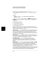
This command specifies a delay time (from 0 to 99999.999 seconds, with
1 ms resolution) between when a channel in the scan list is closed and
the next operation begins (and, if configured, a trigger out pulse is sent).
The delay time can be set individually for each channel in the scan list,
or one delay can be set for all channels in the scan list. Note that, even if
the trigger source is set to IMMediate, the scan list will not advance until
the delay time is met. Following power on or a reset (
*RST
) command,
the delay time is set to “0”.
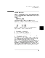
The channel_list can be:
•
a single channel, use
DEL (@snn)
;
•
multiple channels, use
DEL (@snn,snn...)
;
•
sequential channels, use
DEL (@snn:snn)
;
•
groups of sequential channels, use
DEL (@snn:snn,snn:snn)
;
•
or any combination of the above.
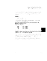
The
ROUTe:CHANnel:DELay?
query returns the delay time of each
channel included in the channel_list. A comma-delineated set of values is
returned. The values are in same order as in the channel_list and in the
form of (snn,snn,mm,...), where snn is the channel number and mm is a
stored channel setup.
Содержание Agilent 3499A
Страница 13: ...1 1 Quick Start ...
Страница 27: ...2 2 Front Panel Operation ...
Страница 55: ...3 3 System Overview ...
Страница 77: ...4 4 Features and Functions ...
Страница 113: ...5 5 Remote Interface Reference ...
Страница 164: ...164 5 ...
Страница 165: ...6 6 Error Messages ...
Страница 173: ...7 7 Plug in Modules ...
Страница 256: ...256 Chapter 7 Plug in Modules 44475A Breadboard Module 7 ...
Страница 261: ...261 Chapter 7 Plug in Modules 44476B Microwave Switch Module 4 7 The 44476B is shown below ...
Страница 268: ...268 Chapter 7 Plug in Modules 44478A B 1 3 GHz Dual 4 to 1 MUX Modules 7 The 44478A B is shown below ...
Страница 286: ...286 Chapter 7 Plug in Modules Terminals and Connections Information 7 ...
Страница 288: ...288 7 ...
Страница 289: ...8 8 Application Programs ...
Страница 299: ...9 9 Specifications ...
Страница 343: ...343 Chapter 9 Specifications 44475A Breadboard Module 4 9 ...

