244
Chapter 7 Plug-in Modules
44472A Dual 4-Channel VHF Switch Module
7
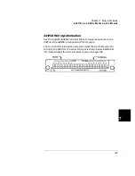
44472A Wiring Information
Regardless of the topology (configuration) you are using, always use 50
Ω
shielded coaxial cables to maintain both characteristic impedance and
isolation. Keep cables as short as possible, especially in high frequency
circuits or pulse circuits where a rise/fall time of less than 50 nsec is
critical. Long cables can add considerable delay time which may cause
timing problems. All test equipment (counters, spectrum analyzers,
oscilloscopes, etc.) must be terminated with a 50
Ω
impedance to
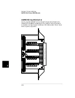
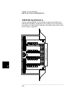
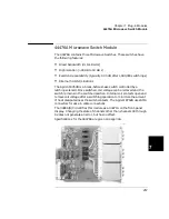
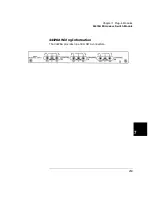
minimize reflection loss. The rear panel is shown below.
Switch Group 0
Switch Group 1
Содержание Agilent 3499A
Страница 13: ...1 1 Quick Start ...
Страница 27: ...2 2 Front Panel Operation ...
Страница 55: ...3 3 System Overview ...
Страница 77: ...4 4 Features and Functions ...
Страница 113: ...5 5 Remote Interface Reference ...
Страница 164: ...164 5 ...
Страница 165: ...6 6 Error Messages ...
Страница 173: ...7 7 Plug in Modules ...
Страница 256: ...256 Chapter 7 Plug in Modules 44475A Breadboard Module 7 ...
Страница 261: ...261 Chapter 7 Plug in Modules 44476B Microwave Switch Module 4 7 The 44476B is shown below ...
Страница 268: ...268 Chapter 7 Plug in Modules 44478A B 1 3 GHz Dual 4 to 1 MUX Modules 7 The 44478A B is shown below ...
Страница 286: ...286 Chapter 7 Plug in Modules Terminals and Connections Information 7 ...
Страница 288: ...288 7 ...
Страница 289: ...8 8 Application Programs ...
Страница 299: ...9 9 Specifications ...
Страница 343: ...343 Chapter 9 Specifications 44475A Breadboard Module 4 9 ...

