Two link two endpoints, select the two lines and then select
Link Selected Annotations
from the
Draw & Measure menu. If the lines have endpoints that are connected it will link them. If they
are not connected, it will select the two closest endpoints, move one so that it is at the same
point as the other, and then link them. Once linked, selecting and moving one endpoint will
move the other as well.
You can unlink annotations by selecting them in the scene tree and using the
Unlink Selected
Annotations
button from the Draw & Measure menu.
8.2
Additional Functions
SceneVision also provides some more specialized functions.
8.2.1
Viewpoint Tool
The Viewpoint tool ‘fixes’ the viewpoint of a 3D model to a particular point in the scene. When
in this viewing mode, you can rotate the viewpoint but you cannot move it. This is used to
simulate what a person would see from a particular position. There are two parts to this tool –
creating viewpoints and switching to the Viewpoint viewing mode.
Creating Viewpoints
You can create a viewpoint from any data or annotation point in a model. Select
Create
Viewpoint
from the Draw & Measure menu or from the toolbar (
). Then, hold
Ctrl
and click
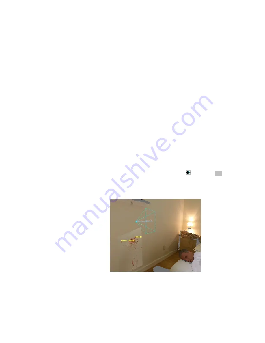
on a point in the model. This will create a pyramid shape called a ‘view frustum’, as shown in
Figure 48, which indicates the location, direction, and field-of-view of the viewpoint. (How to
fix your view to that viewpoint is discussed in the next section.)
Figure 48 Create Viewpoint
Viewpoints are commonly created to correspond with a person’s location – perhaps to
correspond to a person’s eyes 5 ft. above the floor. This kind of viewpoint can be created using
the perpendicular line feature described in section 8.1.7. Create a perpendicular line of a
DeltaSphere-3000 3D Scene Digitizer
67
9/23/05


