Test Your Setup
Before we start creating our own presets, let’s make sure the module is setup properly
by playing back some content from a preset that comes with the module and triggering
playback through external inputs.
Use the Touchscreen to Trigger a Cell
Bitbox mk2 automatically loads the last used preset when you start it up. Trigger
playback of a WAV file by touching a pad in the grid that has a name displayed. You will
see a blue progress bar appear at the bottom of the pad during playback. You will hear
the WAV file played back through the audio output selected for that pad. The default
presets are configure to play out through OUT1 and OUT2.
Trigger a Cell via Control Voltage Signal
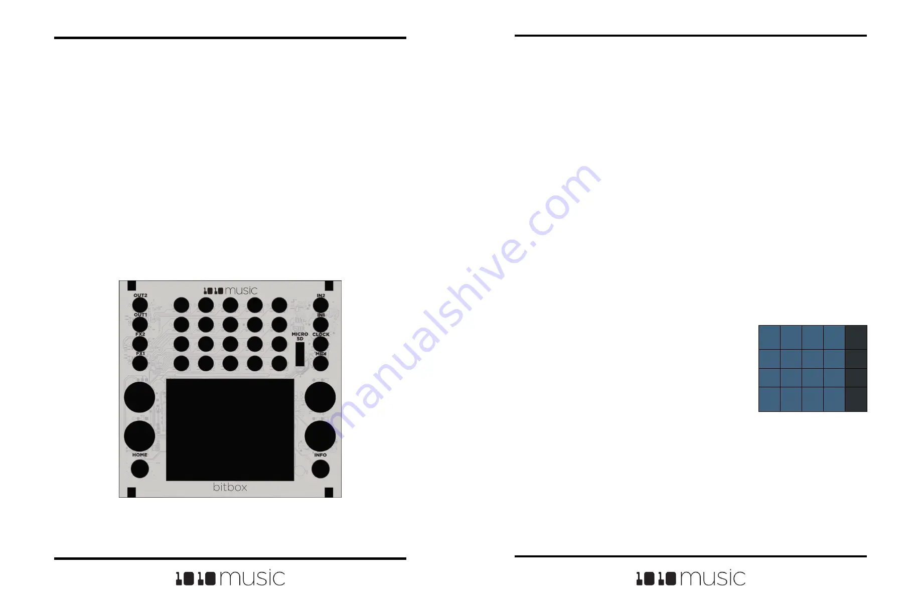
You can use an external signal to trigger the playback of a pad. Plug a trigger source
into one of the CV Trigger jacks. The CV Trigger jacks are mapped to the pads on the
touchscreen. The pad that corresponds to the used CV Trigger jack will now be
triggered when the CV Trigger input receives a high signal of around 5V.
Depending
on the Launch Mode selected for the pad, you may need to send another CV Trigger to
stop playback of the pad.
Trigger a Cell via MIDI Input
You can use MIDI signals to sequence samples and get a
more tactile play mode. Connect your MIDI source to the
MIDI input jack, and configure the MIDI source to use the
channel specified for MIDI Pads in Tools. (See Tools
above to learn how to set the MIDI Pads channel.) Now
you can use the MIDI device to trigger pads. MIDI inputs
for notes 36 to 51 map to the pads in the grid as shown in
the diagram on the right. EXT1 through EXT4 are
assigned notes 55 to 52 for use as Recording triggers.
However, these MIDI mappings for notes 52 to 55 do not
work with modulation.
48
49
50
51
D#3
55
44
45
46
47
54
40
41
42
43
53
36
C2
37
38
39
52
Default Mapping of MIDI
Notes to Bitbox mk2
Cells and EXTs
Copyright 1010music LLC 2023
Page 18 of 97
Page 19 of 97
Copyright 1010music LLC 2023
Bitbox MK2 2.1 User Manual
Mar 1, 2023
Bitbox MK2 2.1 User Manual
Mar 1, 2023
Working in Flipped Mode
When the value for Flip UI is set to ON, the user interface on the touch screen will be
inverted. Use this setting when the module is installed in a rack with the touchscreen on
the bottom. When flipped, the firmware adjusts how the buttons, control knobs and CV
Trigger jacks are mapped to the user interface. One noteworthy change is that the
HOME and INFO buttons now reverse functions. This is done so that HOME is always
on the left and INFO is always on the right. The alignment of the control knobs in this
mode is slightly high compared to the parameters on the touch screen. However, the top
left control knob will control the top left parameter, and the lower right control knob will
control the lower right parameter. The CV trigger inputs are also now mapped to the
inverted display. The input jacks and output jacks maintain their original assignments.
The image below shows the face plate labels for an inverted module.
Inverted Face Plate
At the top of the Tools page, you can see two numbers. The left number (4GB in the
sample screenshots) is the space remaining on the microSD card. The other number
(2.1.2 in the sample screenshots) is the current firmware version number.
When you are done, press the HOME button to go back to the Pads screen.


