223
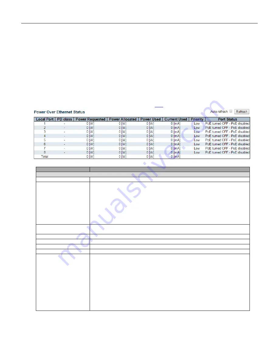
5.4.46 PoE Status
The PoE model(s) supports the IEEE802.3at High Power over Ethernet (PoE) standard.
A powered device (PD) is a device such as an access point or a switch that supports PoE (Power over Ethernet) so
that it can receive power from another device through an Ethernet port.
Note: The POE (Power over Ethernet) devices that supply or receive power and their connected Ethernet
cables must all be completely indoors.
This page allows the user to inspect the current status for all
Object
Description
PoE Status
Local Port
This is the logical port number for this row.
PD Class
Each PD is classified according to a class that defines the maximum power the PD
will use. The PD Class shows the PDs class.
Five Classes are defined:
Class 0: Max. power 15.4 W
Class 1: Max. power 4.0 W
Class 2: Max. power 7.0 W
Class 3: Max. power 15.4 W
Class 4: Max. power 30.0 W
-
displays when the PoE mode is set to
Force-On
on the port(s).
Power Requested
The Power Requested shows the requested amount of power the PD wants to be
reserved.
Power Allocated
The Power Allocated shows the amount of power the switch has allocated for the PD.
Power Used
The Power Used shows how much power the PD currently is using.
Current Used
The Power Used shows how much current the PD currently is using.
Priority
The Priority shows the port's priority configured by the user.
Port Status
The Port Status shows the port's status. The status can be one of the following
values:
PoE not available - No PoE chip found
- PoE not supported for the port.
PoE turned OFF - PoE disabled
- PoE is disabled by user.
PoE turned OFF - Power budget exceeded
- The total requested or used power by
the PDs exceeds the maximum power the Power Supply can deliver, and port(s) with
the lowest priority is/are powered down.
No PD detected
- No PD detected for the port.
PoE turned OFF - PD overload
- The PD has requested or used more power than
the port can deliver, and is powered down.
PoE turned OFF
- PD is off.
Invalid PD
- PD detected, but is not working correctly.
Summary of Contents for RGS Series
Page 7: ...7 Preface Scope Audience Safety Instructions Documentation Conventions ...
Page 9: ...9 Overview Overview Faceplate Panel Introduction ...
Page 13: ...13 Quick Installation Equipment Mounting Cable Connecting Equipment Configuration ...
Page 18: ...18 Figure 6 RGS200 12P Series Ground Connections ...
Page 36: ...36 5 2 1 Configuration Menu ...
Page 37: ...37 5 2 2 Monitor Menu ...
Page 38: ...38 5 2 3 Diagnostics Menu 5 2 4 Maintenance Menu ...
Page 54: ...54 5 3 12 Privilege Level This page provides an overview of the privilege levels ...
Page 238: ...238 Click to re start diagnostics with PING ...
Page 252: ...252 台灣 警告使用者 ...

