30
3.14 DIP Switch Setting for RGS100-5P
Pin No#
Status
5-Port (4TX+1SFP) with PoE
Pin 1
ON
To enable Broadcast storm rate limit
OFF
To disable Broadcast storm rate limit
Pin 2
ON
NOT USED
OFF
NOT USED
3.15 LED Status Indications
Table 1 LED Status Indicators
LED
Name
Indicator
/color
Condition
P1/P2
On Green
P1/P2 power line has power
Off
P1/P2 power line disconnect or does not have power supplied
Alarm
On Red
Ethernet link fails, alarm or power failure alarm occurs
Off
No Ethernet link fails and no power failure alarm
Copper
port
Link/Act
On Green
Ethernet link up but no traffic is detected
Flashing
Green
Ethernet link up and there is traffic detected
Off
Ethernet link down
Copper
port
Speed
On Yellow
A 1000Mbps connection is detected
Off
No link, a 10Mbps or 100 Mbps connection is detected
SFP
port
Link/A
ct
On Green
Ethernet link up
Off
Ethernet link down
SFP
port
Speed
On Yellow
SFP port speed 1000Mbps connection is detected.
Off
No link or a SFP port speed 100Mbps connection is detected
POE
On Green
POE is working
Off
POE is not working
Summary of Contents for RGS Series
Page 7: ...7 Preface Scope Audience Safety Instructions Documentation Conventions ...
Page 9: ...9 Overview Overview Faceplate Panel Introduction ...
Page 13: ...13 Quick Installation Equipment Mounting Cable Connecting Equipment Configuration ...
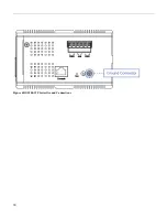
Page 18: ...18 Figure 6 RGS200 12P Series Ground Connections ...
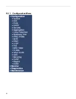
Page 36: ...36 5 2 1 Configuration Menu ...
Page 37: ...37 5 2 2 Monitor Menu ...
Page 38: ...38 5 2 3 Diagnostics Menu 5 2 4 Maintenance Menu ...
Page 54: ...54 5 3 12 Privilege Level This page provides an overview of the privilege levels ...
Page 238: ...238 Click to re start diagnostics with PING ...
Page 252: ...252 台灣 警告使用者 ...

