background image

3D printing workflow

92

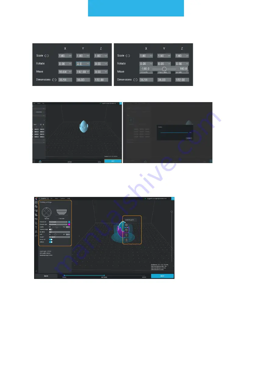
You can set values manually or use sliders.


Set the model according to your preferences and click NEXT to voxelize the model.


The second step of the file preparation is to set the printing parameters.
There are 2 types of menus - global (placed to the left of the screen) and local (opened 
by clicking the right mouse button on the model).


NOTE:

 there can be many different unbound models on the workspace, by clicking the 

right mouse button on them different printing parameters can be selected for each of 
them.

Summary of Contents for VX

Page 1: ...rinting worktable CNC PRO Milling Toolhead Plastic Extruder 3 00 mm Laser PRO Toolhead Plastic Extruder 1 75 mm Thick Paste Extruder Dual PRO Toolhead support zmorph3d com Product Manual ZMorph VX Moo...

Page 2: ...for safe storage and transport 9 2 7 Electromagnetic compatibility EMC 11 2 8 Laser radiation 11 3 Manufacturer s warranty and liability 12 3 1 Scope of the warranty 12 3 2 Acceptance of warranty clai...

Page 3: ...nce and preparation 43 11 5 Presets 46 12 3D printing workflow 49 12 1 Toolheads 49 12 2 3D printing materials 52 12 3 Loading the filament 53 12 4 Material exchanging 60 12 5 Filament replacement dur...

Page 4: ...ro Toolhead 129 14 3 Material fixturing 129 14 4 Laser engraving file preparation 131 14 5 Laser engraving cutting file starting with calibration 135 14 6 Laser PRO safety rules 138 15 Thick Paste Ext...

Page 5: ...18 Firmware upgrades 156 18 1 General informations 156 18 2 Updating firmware 157 19 Help and support 159 19 1 Support request 159 19 2 Troubleshooting 159 19 3 Handy resources 162...

Page 6: ...s every effort to ensure that the safety of use transport storage and disposal is at the highest level However the manu facturer has no direct control over the user and the use of the device therefore...

Page 7: ...specificity ZMorph devices are not intended for use by children under 14 years of age and persons with reduced manual motor and psychomotor skills If the device is operated by handicapped or elderly...

Page 8: ...ice or that are not authorized for use with the toolheads When using ZMorph VX ensure all necessary health and safety measures as de scribed in this manual and separate regulations Handle the sharp ac...

Page 9: ...e worn as there is a risk of fragments of the material scatter ing towards the eyes 2 5 Risk of burns There is a high risk of burns as the temperature of the extruder can be as high as 250 C Do not to...

Page 10: ...t Make sure that it is secured against ejection Recommendations for transportation When placing several devices on a pallet observe the markings on the packaging Protect against moisture Careful fragi...

Page 11: ...not sensitive to interference from other devices systems 2 8 Laser radiation The Laser PRO Toolhead supplied with ZMorph VX is a Class 4 laser with a power of 2 8 Watts and an emitted wavelength of 45...

Page 12: ...resulting from a improper use or application of the product b improper product selection for the existing installation site conditions c improper or inconsistent with User Guide installation includin...

Page 13: ...ZMorph s registered office 3 2 2 Acceptance of warranty claim requires a returning a completed warranty claim during a warranty period to the Service Cen ter b including the name of the product the da...

Page 14: ...le for any damages incurred by the Buyer due to the defect of the product especially damages related to damage of other devices loss of potential benefits or cost of replacement of the product The cla...

Page 15: ...0 PN EN 61000 4 4 2013 PN EN 61000 4 3 2007 PN EN 61000 4 6 2009 PN EN 61000 4 5 2014 PN EN 61000 4 11 2007 The declaration was issued as a result of the conformity assessment procedure conducted with...

Page 16: ...anel which serves as a graphical interface for operation in standalone mode The LCD panel has a port for SD cards on which it is possible to deliver ready made executive files G code files Files can a...

Page 17: ...an be delivered to the device using an SD card or imported to an internal memory using a USB connection You can also transfer a file via Ethernet but the transfer pro cess will be slower To avoid the...

Page 18: ...nstructional solutions of the product It is forbidden to connect the machine to a faulty power supply system It is forbidden to connect the device to the a power outlet without grounding It is forbidd...

Page 19: ...worktable ZMorph VX Laser PRO Thick Paste Extruder 0 3 nozzle 3D printing adhesive 2 mm drill Calibration cable Drill holder SD card power cord spool holder 0 5 kg PLA 0 5 kg PLA Protective goggles 2...

Page 20: ...fication 8 1 Overview Toolhead X carriage Magnetic latches Reset button ON OFF button Spool holder capacity up to 4x1kg spools Worktable clamp release Left frame socket Right frame socket Cooling fan...

Page 21: ...Machine specification 21 Nameplate Power cord socket Ethernet socket USB socket Internal memory card Back overview...

Page 22: ...em driven by a stepper motor and hybrid linear slid ing rails as guiding elements Used for movement of ZMorph VX worktable Must be periodically lubricated to ensure a long life of the machine Z axis a...

Page 23: ...e Toolhead mounting is described in 10 1 part of this manual Y carriage Worktable fixation system specially designed lever and magnets system for quick and effortless changing between additive and sub...

Page 24: ...ning problems like blocked tool head Toolhead changing system quick and repeatable method for mounting different ZMorph toolheads Properly mounted toolhead will ensure high quality fabrication whether...

Page 25: ...head weight 0 60 kg 3D printing specifications Print technology FFF Fused Filament Fabrication Printing head Single material 1 75 mm Dual PRO single nozzle 1 75 mm Single material 3 00 mm Layer resolu...

Page 26: ...l speed 120 mm s Cutting engraving materials Wood wood like leather paper card board felt foil laminate EPP EVA Foam CCL FR4 Milling specifications Toolhead CNC PRO Spindle power 300 W Operating sound...

Page 27: ...Power consumption max 350 W Single extruder power consumption max 220 W Dual extruder power consumption max 230 W CNC Pro milling toolhead power consumption max 330 W Laser Pro toolhead power consumpt...

Page 28: ...be exposed to moisture The electrical installation of ZMorph VX requires it to be connected to a grounded wall outlet Do not use extension cords Leave a 20 mm minimum space from the wall for proper v...

Page 29: ...rph VX Spool holder attachment screws are placed at the top of the frame and highlighted on the picture Loosen the frame screws with a 2 5 mm Allen key 9 2 Safety features removal After the machine ha...

Page 30: ...e screws to the point where you can slide the spool holder Slide the spool holder in place Tighten the screws 9 4 First use When the machine is commissioned for the first time after transport it is ne...

Page 31: ...e to heat up and finish the probing To ensure best calibra tion result print calibra tion pattern Choose Start Take the calibration cable and connect the wider end to the RIGHT frame socket Connect th...

Page 32: ...assembly Select Maintenance Select Change tool Select PARK TOOL wait for positioning process to be finished Disconnect the toolhead cable from the machine frame socket Disconnect the toolhead from the...

Page 33: ...toolhead forward NOTE Tightening the mounting screw without pushing the toolhead to the front might cause the connection between the toolhead and X carriage to be loose This might cause further errors...

Page 34: ...Choose Change tool Choose 3D printing Choose Dual printing Choose Dual PRO CNC PRO Milling Toolhead Connect the LEFT cable to the LEFT frame socket Connect the extruder A cable to X carriage A plug Ch...

Page 35: ...h up to disconnect it from the carriage magnets 10 2 Changing worktable Take the CNC table No tice the magnets under the table are on the prop er side Place the worktable on the carriage magnets will...

Page 36: ...Maintenance 36 Make sure that lever doesn t block the table movement by pulling forward 10 3 Removing covers There are two types of covers front and back covers side covers...

Page 37: ...toward yourself They are snapped via magnets so removing and attaching comes easily The differences between front and back cover are shown in the picture below Front cov er has additional magnets tha...

Page 38: ...from the hooks by gently squeezing the cover Pull out the cover rear corner from the machine frame Pull out the cover upper corner from the machine frame NOTE To mount a cover firstly slide in the upp...

Page 39: ...ard Insert a card on the right hand side of the display NOTE If the user inserted the external SD card the screen should jump forward to the Choose File menu screen on the EXTERNAL directory NOTE If t...

Page 40: ...ose a folder with files from the external SD card Info screen Connecting the machine via Ethernet Connect Ethernet cable to the back of the machine and a computer The information about the IP address...

Page 41: ...ser Connecting the machine via USB Connect the USB cable to the back of the machine and a computer Wait until the computer discovers the machine and installs the drivers If the computer doesn t discov...

Page 42: ...it or MacOS 10 13 or higher Mac Mini 6 0 Late 2012 or later other Apple devices 2014 or later 4GB RAM GPU with OpenGL 3 3 support Internet connection Resolution 1280 x 720 pixels 11 2 Creating Voxeliz...

Page 43: ...m of XXXX XXXX There are two ways of entering the code filling the registration form Have a license code or directly in the Account info in License section Enter license code By filling the form https...

Page 44: ...mport a model in one of the different formats supported for instance an STL In the Scene view it s possible to set its dimensions and orientation When finished click Next In the settings view apply th...

Page 45: ...that a machine will perform It s also possible to inspect the G code instructions and look for possible errors by using the Diagnostic tab Clicking on the Save button results in saving the G code on...

Page 46: ...g Filament Durability Support Laser cutting Material CNC milling Material Operation tool Taking the 3D printing workflow as an example presets can be edited and selected in the SETTINGS view In the Pr...

Page 47: ...customized user presets can be added and modified in tabs dedicated to presets e g Filament preset list There are also other tabs signed by tooth gear icon responsible for durability and support stru...

Page 48: ...on The preset has been duplicated and can be modified depending on the needs After editing preset parameters the changes will save automatically The preset will remain until its deleted To use the new...

Page 49: ...lmost all materials available on the market such as ABS M ABS PLA HIPS Flex PVA PET ASA and similar Single Plastic Extruder 1 75 mm is included in all machine sets Default nozzle is 0 3 mm Toolhead Sp...

Page 50: ...truder 3 0 mm Toolhead being sold separately on special request It operates on 3 mm filaments De fault nozzle is 0 4 mm Cooling fan Nozzle Heating block Thermistor Heat break A plug Pressure adjustmen...

Page 51: ...r manufacturing double material prototypes jigs and fixtures and other high quality models from almost all materials available on the market as ABS M ABS PLA HIPS Flex PVA PET ASA and others Dual PRO...

Page 52: ...motor with planetary gear x2 Extrusion Direct Drive Work area up to 235 x 250 x 165 mm Recommended printing resolution 0 2 mm Supported printing resolution 0 025 0 4 mm Extruder dimensions 170 x 115...

Page 53: ...r You can find out what kind of filament you own by looking at the sticker on the filament roll ZMorph VX package comes with PLA Slide spool on the bar and place it on the ma chine PLA PLA ABS HIPS PL...

Page 54: ...HEAT PLA button will heat the nozzle to 200 C and the PREHEAT ABS to 235 C Take off the front cover Straighten the tip of fila ment up or cut its end Wait till extruder reaches the proper temperature...

Page 55: ...an find out what kind of filament you own by looking at the sticker on the filament roll ZMorph VX package comes with 0 5 kg white and 0 5 kg silver PLA materials Slide spools on the bar and place it...

Page 56: ...cover Straighten the tip of fila ment up or cut its end Wait till extruder reaches the proper temperature The yellow HEATING sign will change colour from yellow to green NOTE The PREHEAT PLA button wi...

Page 57: ...Push the filament down until you feel it has been grabbed by the extruder drive gear Insert the second fila ment into the right side guide hole on top of the extruder Tap the bottom arrow on the scree...

Page 58: ...the toolhead When done choose PLA to preheat the material Wait till extruder reaches the proper temperature The yellow HEATING sign will change colour from yellow to green Tap the LOAD UNLOAD menu Ta...

Page 59: ...e colour from yellow to green Tap the LOAD UNLOAD menu Tap the upper LEFT arrow on the screen to remove 80 mm of the filament At first extruder will load 40 mm to pre vent clogging Tap the upper RIGHT...

Page 60: ...temperature The yellow HEATING sign will change colour from yellow to green Tap the LOAD UNLOAD menu Tap the upper arrow on the screen to remove 80 mm of the filament At first extruder will load 40 m...

Page 61: ...si tion the toolhead When done choose PLA to preheat the material For any other materials than PLA and ABS tem peratures needed to be set up manually Tap the Custom Tem perature button Tap the Left ga...

Page 62: ...pre vent clogging Repeat if needed Third menu named ALL main tain both filaments at the same time Tap upper ar row with ALL description to remove both filaments at the same time Adjust the temperatur...

Page 63: ...re of the extruder will be the same as for the filament that was there before Tap the Left gap in the Target column Tap the needed tempera ture on the keyboard then OK Since the Dual PRO toolhead has...

Page 64: ...on the screen to feed 80 mm of the filament Choose down arrow with LEFT description to do that Push the filament down until you feel it has been grabbed by the extruder drive gear Wait until the mater...

Page 65: ...f needed Tap the upper arrow with RIGHT description on the screen to remove 80 mm of the filament At first extruder will load 40 mm to prevent clogging Repeat if needed Insert new filament gen tly int...

Page 66: ...ary Repeat last 4 steps for down arrow with RIGHT description Remove the extruded material Choose Done and wait until the extrud er starts printing again NOTE Sometimes after clicking DONE the machine...

Page 67: ...n done tap NEXT If your filament is not loaded feed it using arrows on the screen If your filament is already loaded choose Next Wait for the machine to finish printing pattern Choose Maintenance Choo...

Page 68: ...height 0 05 mm with the middle line being the result of the automatic calibration pro cess Detach the autocalibra tion cable Clean the bed Your machine is ready for your first print Look at printed li...

Page 69: ...r 1 or higher 5 Select the best one by pressing their cor responding numbers visible on the screen and clicking APPLY Calibration completed Detach B the cable If after the second round of calibration...

Page 70: ...d prepared NOTE See the toolhead changing process before mounting the Dual PRO extruder on the machine NOTE During the automatic calibration process the printer is heating up Choose Calibrate Choose A...

Page 71: ...inted lines and select the best one on the screen A correct line is the one that sticks to the table after gen tly touching it with the finger but can be easily ripped off with a finger nail NOTE by p...

Page 72: ...ask which of the line is closest to the best result 1 or 5 Pick one and tap NEXT NOTE If none of the printed lines is proper please follow these steps Printer will prepare another 5 lines lower or upp...

Page 73: ...ing screen and advise to repeat the auto matic calibration process or to perform the manual calibration Choose Maintenance Choose Calibrate Choose Manual Wait until the extruder is placed in the right...

Page 74: ...r rubs against the nozzle but it s not too loose NOTE Be very careful using the Move Z axis feature the movement of the Z axis is slow and silent don t press the arrow to many times because it might d...

Page 75: ...the Point1 Set the nozzle at Z 0 for the Point1 move the axis to make the nozzle barely touching the bed Use the arrows to set position To verify the dis tance you should be able to place a sheet of p...

Page 76: ...ll greasy spots We recom mend paper towel and a window cleaner Choose New Job Choose Prepare Bed Wait until the worktable stops Manual 3 point calibra tion process is finished NOTE Move the paper betw...

Page 77: ...er Launch Voxelizer Select the model of your printer when done click the graphic representing machine Co lour of graphic will change to blue and new settings column will appear Apply a thin layer of a...

Page 78: ...3D printing workflow 78 Choose Single 1 75 mm extruder Choose nozzle 0 3 mm This nozzle is mounted in extruder as a default Use an option Remember my choice to save chosen settings...

Page 79: ...marked buttons Select an STL file After importing the file a toolbar will appear on the left that allows basic operations on the mesh model such as scaling SCALE scaling to specific dimensions DIMENSI...

Page 80: ...of the file preparation is to set the printing parameters There are 2 types of menus global placed to the left of the screen and local opened by clicking the right mouse button on the model NOTE ther...

Page 81: ...icon that opens a filament library b Quality is a simplified option to select model quality settings allowing you to select layer height and path width with a single slider HQ guarantees the highest q...

Page 82: ...of the model The path width and default layer height values change to ranges that can be modified again using the Quality slider d Durability settings for the durability of the model This function ta...

Page 83: ...3D printing workflow 83 Hollow Imposes 2 outlines and 0 infill Option for hollow models Light imposes 2 outlines and 3 30 grid type infill...

Page 84: ...3D printing workflow 84 Light honeycomb imposes 2 outlines and 3 50 honeycomb type infill Medium imposes 3 outlines and 30 60 honeycomb type infill...

Page 85: ...n the range defined by Durability The set ting can be edited using the slider or entered manually Generating a preview of the infill is performed on an ongoing basis which allows for a quick assessmen...

Page 86: ...3D printing workflow 86 Lattice Light Solid...

Page 87: ...the angle of inclina tion of the wall under which the support should be generated This is the minimum angle value for the creation of support structures Slide left for more support right for less sup...

Page 88: ...inting workflow 88 After all parameters have been set click NEXT The model is subjected to slicing and as a result gcode file is generated To save it use the SAVE button Dual PRO Extruder Launch Voxel...

Page 89: ...inter when done click the graphic representing machine Co lour of graphic will change to blue and new settings column will appear Choose Dual PRO extruder use arrows to show more toolheads Choose mixi...

Page 90: ...3D printing workflow 90 Use the option Remember my choice to save chosen settings Choose START Import file by using one of marked buttons...

Page 91: ...themselves click YES If you wish to set up the models manually click NO To the left you will find a toolbar that allows various operations on the models The op tions allow for scaling SCALE scaling t...

Page 92: ...p of the file preparation is to set the printing parameters There are 2 types of menus global placed to the left of the screen and local opened by clicking the right mouse button on the model NOTE the...

Page 93: ...peratures a warning message will appear The software will separate the imported models allowing to set individual param eters for both of them To assign filaments left right to the models right mouse...

Page 94: ...settings of 50 guarantee the best ratio of quality to print speed The current path values and layer height are shown under the basic menu Quality can also be defined separately for different models e...

Page 95: ...imposes settings for both models If you want to have different models in both models use the local menu right click on the model you want to edit and change its settings in Local Settings e Infill sel...

Page 96: ...3D printing workflow 96 f Support enable disable the support structure There are 6 types of support dense lattice light...

Page 97: ...3D printing workflow 97 solid solid PVA support dedicated for Dual PRO Extruder tree...

Page 98: ...of the wall under which the support should be generated This is the minimum angle value for the creation of support structures Slide left for more support right for less support g Power raft an option...

Page 99: ...is generated To save it use the SAVE button 12 11 Starting the print After uploading the file to an internal card or inserting an SD card with the file Choose New Job Choose New Job Choose Choose file...

Page 100: ...r selecting the file choose NEXT The table can be pre pared by selecting Prepare Bed and is described in the chapter Preparing the workta ble Choose PLAY Printing will start au tomatically when the ex...

Page 101: ...ament Change function allows you to change the filament during the printout and is described in the chapter Filament replacement during printing Choose Settings The Print Speed part allows you to chan...

Page 102: ...ct LESS or return to the main print ing screen by pressing the BACK button Choose Settings The Print Speed part allows you to change the print speed Select plus to increase or decrease the speed from...

Page 103: ...machine is running press the Pause button on the screen to stop printing Choose Play to contin ue printing The printer will resume the printout exactly where it was stopped Choose More The Heat functi...

Page 104: ...do so choose OK If you do not want to abort the printing choose Back 12 15 Removing a printout from the platform NOTE The spatula has sharp edges that may cause the table to be drawn When taking off t...

Page 105: ...complex geometry additional support is printed which is not part of the mod el When the printout is complete remove them carefully Pliers are best suited for this purpose In case of problems with rem...

Page 106: ...er will ask you to confirm that you want to continue the stopped printout To do so choose YES If you do not want to continue printing choose NO Once the extruder and the table have reached the correct...

Page 107: ...changing collet chuck can be expanded to use up to 7 mm diameter shank cutters Main elements of CNC Pro toolhead Spindle in steel casing Aluminium mounting base ER11 collet mounting chuck Toolhead cab...

Page 108: ...elling board styrodur To explore all materials please follow this link to ZMorph Materials Library https zmorph3d com product materials 13 3 Material fixturing For proper material fixturing during CNC...

Page 109: ...4 threaded holes for mounting your material with M4 screws Types of workholding solutions Your workholding solution should be adapted to material and its dimensions to ensure best results T slots for...

Page 110: ...er to use Only for flat sheet materials like plywood Step clamps Sheet material Block material 2 5 Allow for mounting mate rials of different heights Stick out above material surface Vises Block mater...

Page 111: ...o 17 mm and hold down the collet fastening nut Loosen the nut Take out the old cutter if any is inserted Put in a new cutter En sure that it is inserted at least 15 mm deep Firmly tighten the collet n...

Page 112: ...ling Open Voxelizer 2 0 software and choose ZMorph VX machine CNC PRO Toolhead and 2D Milling operation Click START Set material dimensions to match Raw material that would be used for milling Change...

Page 113: ...CNC milling workflow 113 Import your DXF file Now the drawing can be freely moved scaled and rotated on the table preview...

Page 114: ...Click NEXT when ready You will me automatically moved to SETTINGS tab Choose material from drop down list and Set Safe height for travel remember to take into account any fixtures that might stick ou...

Page 115: ...like to mill your drawing with Choose operation tool Parameters are set by default adjust them according to your needs Apply operation settings to chosen parts of the drawing When all operations are r...

Page 116: ...6 Now you can check generated G code and save it Start your file according to 13 6 part of the manual 3D Milling Open Voxelizer 2 0 software and choose ZMorph VX machine CNC PRO Toolhead and 2D Millin...

Page 117: ...CNC milling workflow 117 Set material dimensions to match Raw material that would be used for milling Change material position to LEFT along the X axis and FRONT along Y axis Import your DXF file...

Page 118: ...caled and rotated on the table preview Click NEXT when ready You will me automatically moved to SETTINGS tab Choose material from drop down list and Set Safe height for travel remember to take into ac...

Page 119: ...like to mill your drawing with Choose operation tool Parameters are set by default adjust them according to your needs Apply operation settings to chosen parts of the drawing When all operations are r...

Page 120: ...o the Choose file section Files uploaded to the in ternal SD card are locat ed in the INTERNAL tab files uploaded to the SD card are located in the EXTERNAL tab After uploading the file to an internal...

Page 121: ...g the calibration process may result in damaging the milling cutter machine or the toolhead and after that hurting the user Select the prepared Gcode file If the prepared file or folder is not visible...

Page 122: ...red in the motherboard internal memory That is guided by the fact that this value is not easy to change manually by the user unlike the X and Y axes NOTE Don t home the Z axis when the milling cutter...

Page 123: ...ft front corner NOTE Toggle the distance button for better control over the cutter When the cutter is in its local position go to the SET menu and set the local 0 0 0 coordinates by pressing the Set X...

Page 124: ...file Choose NEXT when ready Close covers The ma chine will go back to milling operations If you selected start procedure you will be walked through the pro cess Using arrows move the toolhead to conve...

Page 125: ...k the entrance to the room where a machine with the CNC PRO toolhead is with a proper sign saying that eye protection is required Ear protection required sign When working with the device with the spi...

Page 126: ...X machine with the CNC PRO toolhead without covers both operators and bystanders must always wear safety goggles failure to do so may re sult in eye damage Safety at work Do not place your hands in th...

Page 127: ...is being changed Do not touch electrical parts with wet hands Warning signs Caution Danger from moving parts To avoid injury or damage to parts of the body do not reach inside the unit or insert any f...

Page 128: ...ment of the tool head to X carriage of ZMorph VX machine Main elements of Laser PRO Toolhead Covering tube Aluminium mounting base Toolhead cables Aliminium casing Specification Construction High qual...

Page 129: ...workspace of ZMorph VX there are T slots milled for mount ing your workholding with M4 screws and square nuts For materials larger than workspace of ZMorph VX there are M4 threaded holes for mounting...

Page 130: ...Laser cutting and engraving workflow 130 T slots for M4 screw square nut based fixturing M4 threaded holes for out of workspace fixturing...

Page 131: ...s not stick out above mate rial surface Surface must be scraped of tape residues Sheet clamps added to ZMorph VX Sheet material 3 5 Can be cus tom 3d printed Harder to use Only for flat sheet material...

Page 132: ...ser cutting and engraving workflow 132 Set material dimensions to match Raw material that would be used for engraving or cutting Change material position to LEFT along the X axis and FRONT along Y axi...

Page 133: ...cutting and engraving workflow 133 Import your DXF file Now the drawing can be freely moved scaled and rotated on the table preview Click NEXT when ready You will be automatically moved to the SETTING...

Page 134: ...or travel remember to take into account any fixtures that might stick out over material surface Choose an operation that you would like to engrave your drawing with Parameters are set by default adjus...

Page 135: ...th the pre pared file Enter the New Job menu Go to the Choose file section Files uploaded to the in ternal SD card are locat ed in the INTERNAL tab files uploaded to the SD card are located in the EXT...

Page 136: ...re starting the Laser engraving cutting process the machine must be calibrated to the mounted material on the worktable Skipping the calibration process may result in damaging the machine or the toolh...

Page 137: ...e spindle and when there is material on the CNC work table This will damage the milling cutter and might disar range the Z axis motors Press the Home X and Home Y buttons Watch out for your cutter not...

Page 138: ...iratory tract and eyes Workstation Avoid using any reflective surface in the room in which the laser is used eg mirrors equipment with shiny metal chromed nickel plated aluminized or glass parts It is...

Page 139: ...h the eye and it is a radiation level that is completely safe for the human eye Provide personnel and bystanders staying in the room where the laser device works with mouth and nose masks equipped wit...

Page 140: ...machine with Laser PRO make sure that the ma chine s surroundings work room is closed and that there is no possibility of unauthorized access without proper eye protection 2 Safety at work with Laser...

Page 141: ...direct or reflected enters the eye Avoid skin exposure Avoid exposure to skin and sensitive materials A Class 4 laser can burn skin and materials especially dark and or lightweight materials at close...

Page 142: ...unting base Piston Cables Syringe Stepper motor Specification Construction 3 mm aluminum base with ABS printed parts Nozzle 2 mm 4 mm Motor Nema 17 stepper motor Default work speed 10 mm s depends on...

Page 143: ...e piston inside the syringe and lock the syringe blockade 15 3 Material application 15 2 Materials Thick Paste Extruder has a wide potential for experimental applications in art projects material rese...

Page 144: ...ne Enter the Maintenance menu Go back to the main menu screen Enter the New Job Choose file and press NEXT button Go to the Settings op tion Push the extrude ex tract paste button until the paste flow...

Page 145: ...e the Move x y z buttons to maneuver the Thick Paste syringe to be 1mm above the front left corner of the table Choose your Gcode file and press NEXT Go to the Calibrate option Press the SET button Ch...

Page 146: ...eparation Open Voxelizer 2 0 software choose ZMorph VX machine and Thick Paste Extruder tool head Click START Return to the SET page Press all the SET x y z 0 button to define the local zero points Pr...

Page 147: ...Thick Paste Extruder workflow 147 Import DXF File Now the drawing can be freely moved scaled and rotated on the table preview...

Page 148: ...ick Paste Extruder workflow 148 Click NEXT when ready You will be automatically moved to settings tab of software Set operation parameters according to paste you would like to use Click NEXT when read...

Page 149: ...t and start your work 15 6 File starting Copy gcode file to external SD card Turn on the machine Tap new job button Tap Choose file button Choose your prepared gcode file from external source Click Ne...

Page 150: ...th the Thick Paste Extruder are not certified as edible Do not inject any hard and solid materials inside of the Thick Paste syringe It may damage the Thick Paste Extruder Do not place your hands in t...

Page 151: ...tools and their frequency 16 2 General procedures To Do Tools Frequency Solution Cleaning the work area from model residues and chips vacuum cleaner fast evaporating cleaners conta ining alcohol comp...

Page 152: ...es To Do Tools Frequency Solution Cleaning the nozzle surface from dirt and ma terial residues tweezers wire brush Before each job Remove any residual material from the heated nozzle with tweezers If...

Page 153: ...ning the X and Z axis rails from dirt and lubricating them lubricating oil PTFE grease dry cloth paper towel Every 2500 working hours This is done while the machine is swit ched off Apply some grease...

Page 154: ...is screws just above the Z axis lifts and then use the LCD interface to move the Z axis up and down to distribute the grease through the screws Lack of proper axis maintenance may have an impact on th...

Page 155: ...ed roller Single Extruder 3 00 mm toolhead Nozzle 0 2 0 3 0 4 mm Single Extruder 1 75 mm toolhead Nozzle 0 3 0 4 mm Single Extruder 3 00 mm toolhead Nozzle 0 4 mm Dual PRO 1 75 toolhead Borosilicate g...

Page 156: ...7 VX 1 0 1 means that firm ware running on the machines is versioned 1 0 1 The information about new firmware release is always published at our website social media and via newsletter so be sure to f...

Page 157: ...urn off or reset the printer during this process After update finishes the machine should restart itself Prepare a SD card Download the newest firmware archive file with zip extension from Zmorph Know...

Page 158: ...es to proceed and skip countdown he machine will start up dating the LCD screens You must not remove the SD card turn off or reset the printer during this process This pro cess may take up to 60 minut...

Page 159: ...if it occur in front LCD screen Video or photo which shows the problem is not required but it will help us to solve your problem faster If you have a print quality problem please provide information...

Page 160: ...the gcode file is designed correctly Check if the thermistor is correctly instal led inside the heating block No connection via USB PC is not detecting the machi ne Check the USB cable with other dev...

Page 161: ...sure that nothing is blocking the axes before new job Calibration result inaccurate Inaccurate result of the auto calibration Check if the work table is aligned correc tly Check if the X axis is level...

Page 162: ...izer Software https voxelizer com ZMorph s original Voxelizer software is the intelligence behind the machine It allows you to control all fabrication methods of ZMorph VX and gives you access to the...

Page 163: ...zmorph3d com...

Reviews: