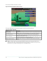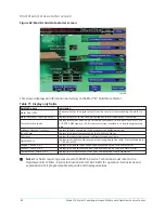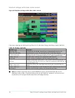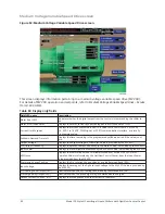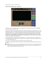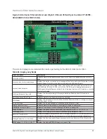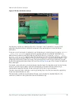
Variable Speed Drive screen
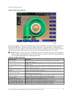
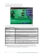
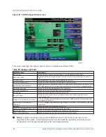
Figure 51: Variable Speed Drive screen
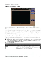
This screen displays information pertaining to a variable speed drive (VSD).
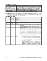
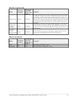
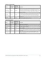
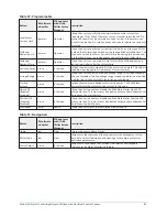
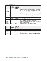
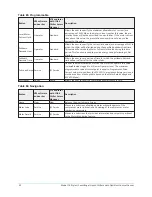
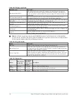
Table 80: Display only fields
Field/LED name
Description
PRV Position
Displays the Pre-rotation Vane position as a value between 0 and 100%.
Motor Run (LED)
Indicates whether the digital output from the controls is commanding the motor to
RUN.
VSD Fault (LED)
Illuminates when a faulty condition exists with the VSD.
Input % Full Load Amps
Displays the input current as a percentage of the FLA value.
Input Current Limit Setpoint
Displays the current limit value in use. This value could come from a 0 to 20mA, 0 to 10
VDC, PWM signal or SC-EQ communication interface, or a locally programmed value.
VSD Output Voltage
Displays the output voltage measured to the motor.
VSD Output Frequency
Displays the present output frequency to the motor.
Input Power
Displays the total kilowatts measured by the VSD.
Input kW Hours
Displays the cumulative amount of kilowatts used over time as the VSD motor
controller operates.
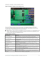
Voltage Total Harmonic Distortion
(L1, L2, L3) Displays the Total Harmonic Distortion (THD) for each of the voltage lines
as calculated by the VSD.
Input Current Total Demand
Distortion
(L1, L2, L3) Displays the calculated Total Dynamic Distortion (TDD) for each of the input
current lines.
Input kVA
Displays the Input kVA measured by the VSD.
Output Current (RMS) Phase A, B, C Displays the phase current measured to the motor.
Input Power Factor
Displays the relationship between Input Power and Supply kVA.
Motor % Full Load Amps
Displays the motor current as a percentage of the FLA value.
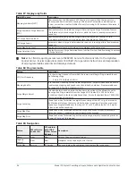
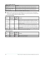
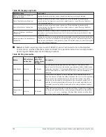
Note:
For fields requiring access level of SERVICE. Service Technicians must refer to the
OptiView Control Center - Service Instructions (Form 160.76-M1)
for operation instructions and
explanation of all programmable setpoints and displayed values.
Model YK Style H Centrifugal Liquid Chillers with OptiView Control Center
88

