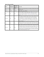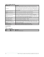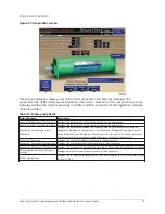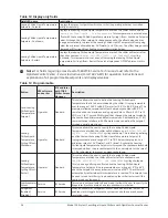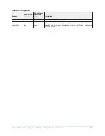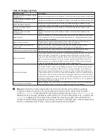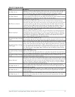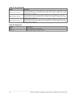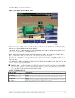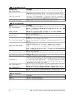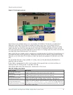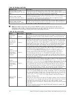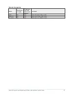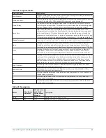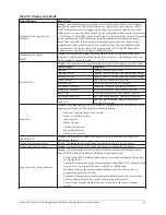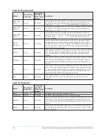
Table 19: Programmable
Button
Description
Hot Water Control
(Enabled or Disabled; default Disabled) Allows the Service Technician to enable and disable
the Hot Water Control for the Heat Recovery feature. When enabled, Control Valve will
control the Return Condenser Liquid Temperature to achieve the Hot Water Setpoint.
Hot Water Setpoint
(65.0 to 125°F extended range, 65.0 to 112°F standard range; default 95°F)
Sets the temperature to which the Control Valve will control the Leaving Heating Condenser
Liquid Temperature. Only appears when Hot Water Control is enabled.
Head Pressure Setpoint
(15.0 to 60 PSID; default 23.0 PSID)
Sets the pressure differential to which the Control Valve will control the Head Pressure.
When both Hot Water Control and Head Pressure Control are enabled, the Control Valve will
normally be performing Heat Recovery (controlling to the Hot Water Setpoint). However,
it will switch over to Head Pressure Control when certain operating conditions are met as
shown in the flow chart in the Heat Recovery Section in
OptiView Control Center – Service
Instructions (Form 160.76-M1)
. Only appears when Head Pressure Control is enabled.
Remote Input Type
(0 to 10V or 4 to 20mA; default 0 to 10V)
When operating in Analog Control Source, the LTC I/O Board accepts a Remote Hot Water
Setpoint offset in the form of either a 0 to 10 VDC or 4 to 20mA input to the LTC I/O Board
input (TB9-3/4). This setpoint configures the LTC I/O Board input to accept the input signal
type applied. Only appears when the Hot Water Control is set enabled and the Control
Source Setpoint (OPERATIONS Screen) is set to Analog.
Control Valve Output Settings
– Type
(0 to 10V or 4 to 20mA; default 0 to 10V)
Sets the output signal to the Control Valve to be in the form of either 0 to 10 VDC or 4 to
20mA. Only appears when Hot Water Control is enabled or Head Pressure Control is enabled.
Control Valve Output Settings
– PID Output
(Direct or Reverse) Allows the output signal to the Control Valve to be set to direct or reverse
acting. When set to direct, the voltage or current signal to the Control Valve is at minimum
for a 0% command and at maximum for a 100% command. When set to reverse, the voltage
or current signal to the Control Valve is at maximum for a 0% command and at minimum
for a 100% command. Only appears when Hot Water Control is enabled or Head Pressure
Control is enabled.
Control Valve Output Settings
– Set
(0.0% to 100%; default 0.0%)
Allows the Control Valve to be manually set to a pre-determined position between 0.0% and
100%. Only appears when Hot Water Control is enabled or Head Pressure Control is enabled.
Control Valve Output Settings
– Auto
Places the Control Valve in automatic control. Only appears when Hot Water Control is
enabled or Head Pressure Control is enabled.
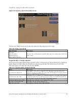
Change Setpoints
Use to enter the Hot Water Control and Head Pressure Control PID variables below. Pressing
this key places a green box around the first changeable setpoint. Use the up/down, left/right
arrows to place the selection box around the desired setpoint. With the setpoint selected,
press the ENTER key. A dialog box appears with the range of settings. Using the NUMERIC
keys, enter desired value. Then press the ENTER key.
Hot Water Control – P
Sets the Proportional Gain of the Hot Water Control (0.00 to 5.00; default 2.00). Use the
Change Setpoints key as described above to select/enter this setpoint. Appears when Hot
Water Control is enabled.
Hot Water Control – I
Sets the Integral Gain of the Hot Water Control (0.00 to 5.00; default 2.00). Use the Change
Setpoints key as described above to select/enter this setpoint. Appears when Hot Water
Control is enabled.
Hot Water Control – D
Sets the Derivative Gain of the Hot Water Control (0.00 to 5.00; default 0.00). Use the Change
Setpoints key as described above to select/enter this setpoint. Appears when Hot Water
Control is enabled.
41
Model YK Style H Centrifugal Liquid Chillers with OptiView Control Center

