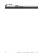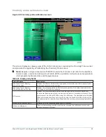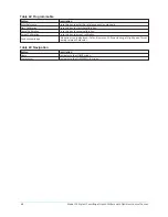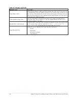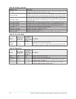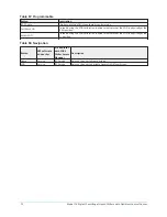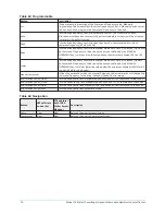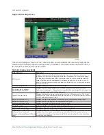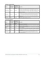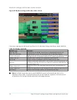
Table 53: Display only fields
Field/LED name
Description
Surge Avoidance Surge Detected
(LED)
Illuminates momentarily when a surge is detected by the Surge Protection feature. If
equipped with a VSD or MV VSD, these are only the surges detected while the drive is
running at maximum frequency.
ACC Surge Detected (LED)
Only displayed if equipped with a VSD or MV VSD. Illuminates momentarily when a
surge is detected by the ACC function in the Microboard, while the drive is running at
less than maximum frequency.
Stall Count
Displays the number of times the Stall Detector Board output voltage goes above the
High Limit Setpoint. The count can be reset with an ADMIN access level password.
Stall Time ( __Days __Hrs __Min __Sec) Displays the accumulated time the Stall Detector Board output voltage is greater than
the High Limit Setpoint while the chiller is running.
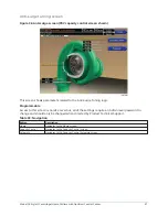
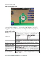
VGD Control State
Displays the current state of the VGD control. The states are: Stall Waiting, Probing,
Stall Reacting, Surge Reacting, Surge Waiting, Hot Gas Hold, Hot Gas Override, Sensor
Failure Override, Extreme Stall Override, Manual Hold, Manual Open, Manual Close.
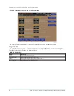
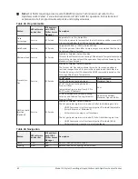
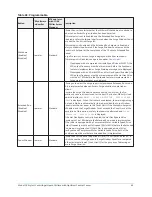
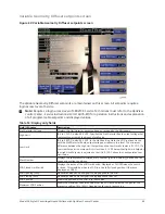
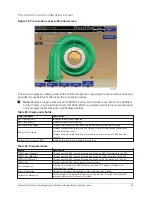
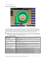
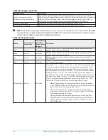
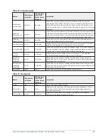
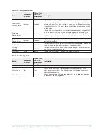
Table 54: Programmable
Button
Description
Extreme Stall Duration
(10 to 20 minutes; default 10) – Specifies the maximum allowed time an extreme stall
condition can exist before the VGD operation is disabled and driven to the full open
position to protect it from damage.
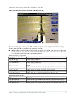
PRV VGD Inhibit
(40% - 100% default 100%) – While the Pre-rotation Vanes position is greater than this
setpoint, extreme stall conditions are not checked, the VGD control is inhibited and the
VGD is pulsed open according to the Open Pulse Setpoint. While this is in effect, PRV
Position Override is displayed as Control Status.
PRV Offset
(0 to 5%; default 3) – If the VGD control is in the Stall Waiting state and the Pre-rotation
Vanes position changes by more than this value, the Probing state will be entered.
If the PRV Offset is set to 0%, the Stall Waiting state is performed based only on the
Probe Wait Time setpoint interval.
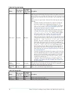
Surge React Time
(1 to 30 seconds; default 5) – Specifies the length of the close pulse applied to the VGD
in response to a surge.
Surge Wait Time
(0.5 to 5 minutes; default 3) – Specifies how long the VGD control remains in the Surge
Waiting state before entering the Probing state.
Stall Wait Time
(0.5 to 5 minutes; default 3) – Specifies how long the VGD control remains in the Stall
Waiting state before entering the Probing state.
Open Pulse
(1 to 9 seconds; default 2) – Specifies the length of the open pulse applied to the VGD
during 10 second periods while in the Probing state.
High Limit
(0.5 to 1.2 VDC; default 0.6 VDC; Specifies the Stall Detector Board output voltage that
represents an acceptable amount of stall noise.
Low Limit
(0.4 to 0.8 VDC; default 0.5 VDC; In the Stall Reacting State, the VGD is driven closed
until the Stall Detector Board output voltage decreases to this level.
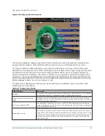
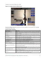
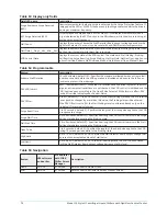
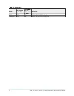
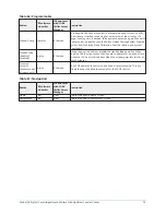
Table 55: Navigation
Button
V09 software
and earlier
V10 and later
with YORK
Chiller Access
Manager
Description
Home
Service
JCI Service
Returns user to Home screen.
VGD
Service
JCI Service
Returns user to Variable Geometry Diffuser screen.
Model YK Style H Centrifugal Liquid Chillers with OptiView Control Center
70

