265
SECTION 32 - MOTOR MONITORING
FORM 160.54-M1
ISSUE DATE: 10/25/2019
JOHNSON CONTROLS
JCI COMPANY CONFIDENTIAL
32
When either of the enabled motor bearing temperatures
exceeds the programmed High Bearing Temperature
Warning for 3 continuous seconds, Warning Motor
High Bearing Temperature is displayed. This warn-
ing will automatically clear when both bearing tem-
peratures decrease below the warning threshold. This
warning will not occur when the Bearing Temperature
Protection setpoint is set to disabled on the MOTOR
DETAILS Screen. Also, it will not act on any RTD in-
put registering as an open RTD.
When either of the enabled bearing temperatures ex-
ceed the programmed High Bearing Temperature Shut-
down threshold for 3 continuous seconds, a safety
shutdown is performed and Motor High Bearing Tem-
perature is displayed. The chiller can be restarted after
both bearing temperatures decrease to at least 9°F be-
low the shutdown threshold and the COMPRESSOR
Switch is placed in the Stop-Reset position. This safety
shutdown will not occur when the Bearing Tempera-
ture Protection setpoint is set to disabled on the MO-
TOR DETAILS Screen. Also, it will not act on any
RTD input registering as an open RTD.
See
for RTD resistance/voltage
for Thermistor resis-
tance/voltage table.
VIBRATION
The motor bearing vibration is monitored with accel-
erometers. Both the shaft end and opposite shaft end
bearings are monitored. The -001 board is required.
The Bearing Vibration Protection setpoint must be
set to the sensor type that is used. Once set, the mi-
croboard via serial communications, commands the
Motor Monitoring Board to read the appropriate sen-
sor inputs and it also sends configuration commands as
below. If set to any setting other than DISABLED, the
respective vibration values are displayed on the MO-
TOR DETAILS Screen. The settings are:
• DISABLED - Disables the Bearing Vibration
Protection feature. No bearing vibration values
are displayed and the heading, text and data boxes
do not appear. The High Bearing Vibration Fault,
Warning and Baseline Not Set Warning will not
occur. This setting is used when the motor is not
equipped with bearing vibration sensors or if is
desired to disable the feature for service reasons.
This is the default setting. The Motor Monitoring
Board is commanded to not read any of its vibra-
tion sensor inputs.
• ROLLING ELEMENT - Enables and displays the
Bearing Vibration Protection feature. Displays the
shaft end and opposite shaft end vibration values
as reported by the vibration sensors via the Motor
Monitoring Board serial communications. The Vi-
bration Baseline values, created by either manual
entry or by running the auto baseline routine are
shown, along with the Auto Baseline and Auto
Baseline setpoint keys. The microboard sends a
command to have the Motor Monitoring Board
read the sensor inputs at the following points and
another command to set the gain of these inputs.
The Gain value [1;1, 11:1, 21:1(default)] sent is
the value set with the Vibration Gain setpoint (on
the MOTOR SETPOINTS Screen).
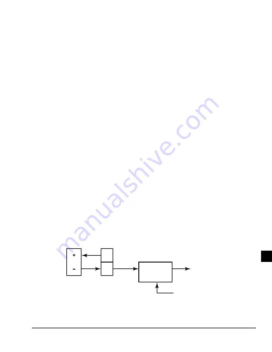
VIBRATION ANALOG INPUTS
FIGURE 103 -
BEARING VIBRATION SENSOR
NOTES
Shaft end connection shown. Typical of opposite shaft end input.
GAIN SELECT
FROM PROCESSOR
GAIN
1:1, 11:1, 21:1
TB3
2
1
+V
IN
LD15006


