


244
FORM 160.54-M1
ISSUE DATE: 10/25/2019
SECTION 29 - HEAD PRESSURE CONTROL
JCI COMPANY CONFIDENTIAL
JOHNSON CONTROLS
The evaporator and condenser transducers are connect-
ed to the microboard as shown in
This provides the head pressure (condenser mi-
nus evaporator) to the microboard. The Head Pressure
Control Valve is driven from the LTC I/O Board 031-
02895-000. The operation of this board is explained in
SECTION 27 - LARGE TONNAGE CHILLER (LTC)
. The microboard
communicates with this board using RS-485 Modbus
serial communications. It sends the valve positioning
command, via this serial link, to the I/O Board where it
is converted to a 0 to 10 VDC or 4 to 20mA positioning
signal that is applied to the valve as described below.
CONTROL
When Head Pressure Control is enabled, all the follow-
ing programmable settings and applicable parameters
are available on the HEAD PRESSURE CONTROL
Screen (or HEAT RECOVERY Screen, if Heat Recov-
ery is enabled).
Setpoints
• Head Pressure setpoint (15.0 psid to 60.0 psid;
default 23 psid) - Sets the Head Pressure that the
control will control to. Value entered is displayed
as Head Pressure setpoint.
• Control Valve Output Settings:
TYPE – Makes the control signal to the Head
Pressure Control Valve either 0 to 10 VDC or
4-10mA (default 0 to 10 VDC).
PID OUTPUT – Makes the control signal to
the Head Pressure Control Valve either Di-
rect or Reverse acting (default Direct). Set to
Direct for this application.
SET – Is used to manually set the Head Pres-
sure Control Valve to any position between
0.0% and 100%.
AUTO – Returns the Head Pressure Control
Valve to Automatic Control Mode (default
Auto).
• Head Pressure Control – Sets the proportional
gain of the control:
P- Sets the proportional gain of the control
over the range of 0.00 to 5.00(default 2.00).
I – Sets the integral gain of the control over
the range of 0.0 to 5.00 (default 2.00).
D – Sets the derivative gain of the control
over the range of 0.0 to 5.00 (default 0.00).
When Head Pressure Control is enabled, the Control
Valve Output is modulated by a direct acting PID con-
trol. The inputs to the PID control are the chiller Head
Pressure (Condenser Pressure – Evaporator Pressure)
and the Head Pressure setpoint. The PID control er-
ror is defined as Head Pressure setpoint – Head Pres-
sure. The PID control’s proportional, integral and de-
rivative gains are programmable using the CHANGE
SETPOINTS key. The Control Valve position is dis-
played as 0.0% to 100% in the box labeled CONTROL
VALVE OUTPUT. The control output to the valve is
direct acting (as the Head Pressure increases above the
setpoint, the valve is driven more open to provide less
tower bypass or more flow through the condenser).
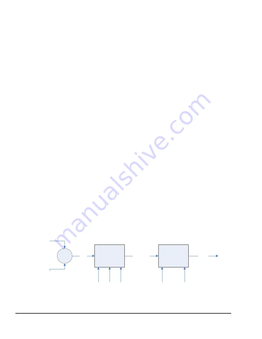
The following diagram shows the PID controller.
LD27943
+
-
PID
Control
Error
Analog
Output
Conditioning
PID Control
Output
Analog
Output
Head Pressure
Setpoint
Head Pressure
(Delta P)
(0.0–100.0%)
(0-10V,
10-0V,
4-20mA [2-10V],
20-4mA [10-2V])
P
I
D
(PID Gains)
Type
(0-10V,
4-20mA)
Output
(Direct,
Reverse)
FIGURE 96 -
HEAD PRESSURE CONTROL FLOW DIAGRAM


