YORK INTERNATIONAL
42
FORM 100.50-NOM1 (604)
Startup
Post Start Checks:
• When a signal is received at the gas heat con trol
mod ule from the Primary Unit Controller, verify:
◦
Combustion blower starts and runs for 30 sec-
onds.
◦
Spark igniter sparks continuously.
◦
Gas valve opens.
◦
Burners light from right to left, in a 2-5 second
time frame, that each one lights in sequential
order from right to left, establishes stable
ß
ame
immediately upon ignition.
◦
Flame is stable, with ignition starting at the end of
the burner and that no burning is oc cur ring inside
the burner.
◦
There will be some noise on startup with units
that have a thermostat, as the full burner operation
will oc cur, skipping the low
Þ
re ignition startup,
last ing for ap prox i mate ly 20 sec, with the burner
noise re duc tion no tice able at this point. There may
also be some smoke thru the
ß
ue, due to tool ing
oil burn ing off of the heat exchanger tub ing.
• Ignition control operation is as follows:
◦
Once the control receives a signal from the Pri-
mary Unit Controller for heat, the combustion
blower starts for a 30 sec. pre-purge.
◦
The spark igniter is then energized with the gas
valve opening; it will try for ignition for 7 sec-
onds.
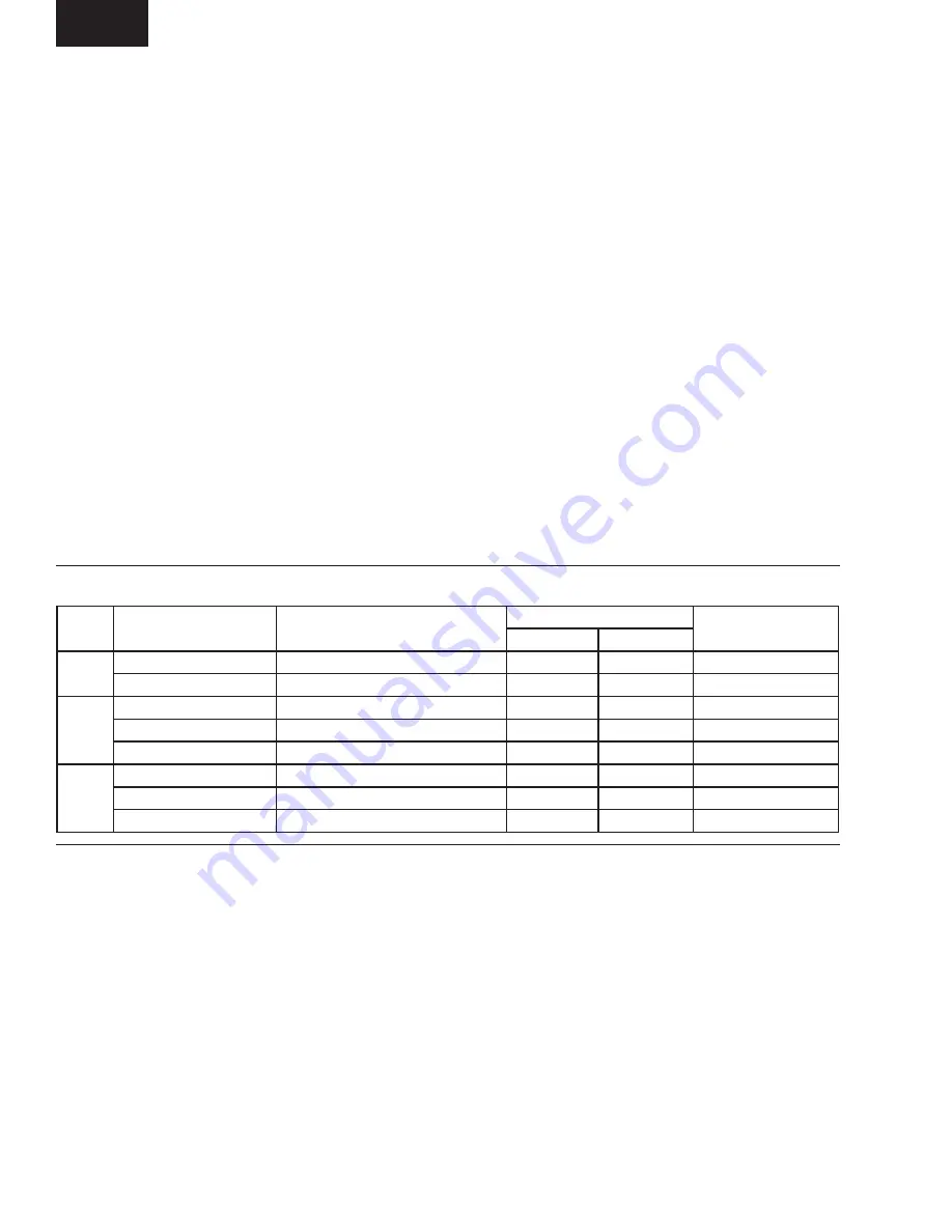
TABLE 7 – GAS HEAT PERFORMANCE DATA
◦
The control will look for the remote
ß
ame sensor
prov ing
ß
ame.
◦
If it does prove, the burners will con tin ue; if not,
the gas valve will be closed, there will be a 30 sec-
ond purge period; the igniter will again energize
and gas valve will open for 7 secs; there will be
3 tries for ignition; after 3 tries, the control will
lock out.
◦
The control will also restart the pro cess if the
rollout switch(es) (2 switches, located above the
burn ers) opened and have been reset, indicating
burning in side the burners and/or outside of the
heat ex chang er tubing.
◦
Rollout switches are manual reset, and need to
physically reset if they open for any rea son. This
is be cause the problem is usually blockage of
the
ß
ue pas sag es and service personnel needs to
observe the pas sag es
Þ
rst hand.
◦
The control circuit is tested in the fac to ry to insure
that all of these steps are followed, however, nat-
u ral gas is not actually in tro duced to the sys tem
in the plant; ni tro gen is used in its place.
Gas pressures should be as follows:
• Entering pressure to the gas valve:
Natural
Gas
4.5” WC min, 13.5” WC maximum
Propane
11” WC min, 13.5” WC maximum
• Manifold Pressure (leaving gas valve):
Natural
Low Fire, manifold pressure = 1.2” WC.
High Fire, manifold pressure = 3.5” WC.
Propane
Low Fire, manifold pressure = 2.4” WC.
High Fire, manifold pressure = 10.0” WC.
• All pressures have a tolerance of +/- 0.3” WC.
UNIT
GAS INPUT CAPACITY
(BTU/HR X 1000)
MAXIMUM OUTPUT CAPACITY
(BTU/HR X 1000)
AIRFLOW
TEMP. RISE
(°F)
MIN.
MAX.
50-65
375
300
6,950
27,750
10-40
750
600
11,150
27,750
20-50
70-85
375
300
6,950
27,750
10-40
750
600
11,150
27,750
20-50
1125
900
15,150
33,325
25-55
90-95
375
300
6,950
27,750
10-40
750
600
11,150
27,750
20-50
1125
900
15,150
33,325
25-55


