YOKOGAWA VZ20X User Manual Download Page 132


8-17 


IM 77V01B01-01EN 

5th Edition: 2023.03.07-00 


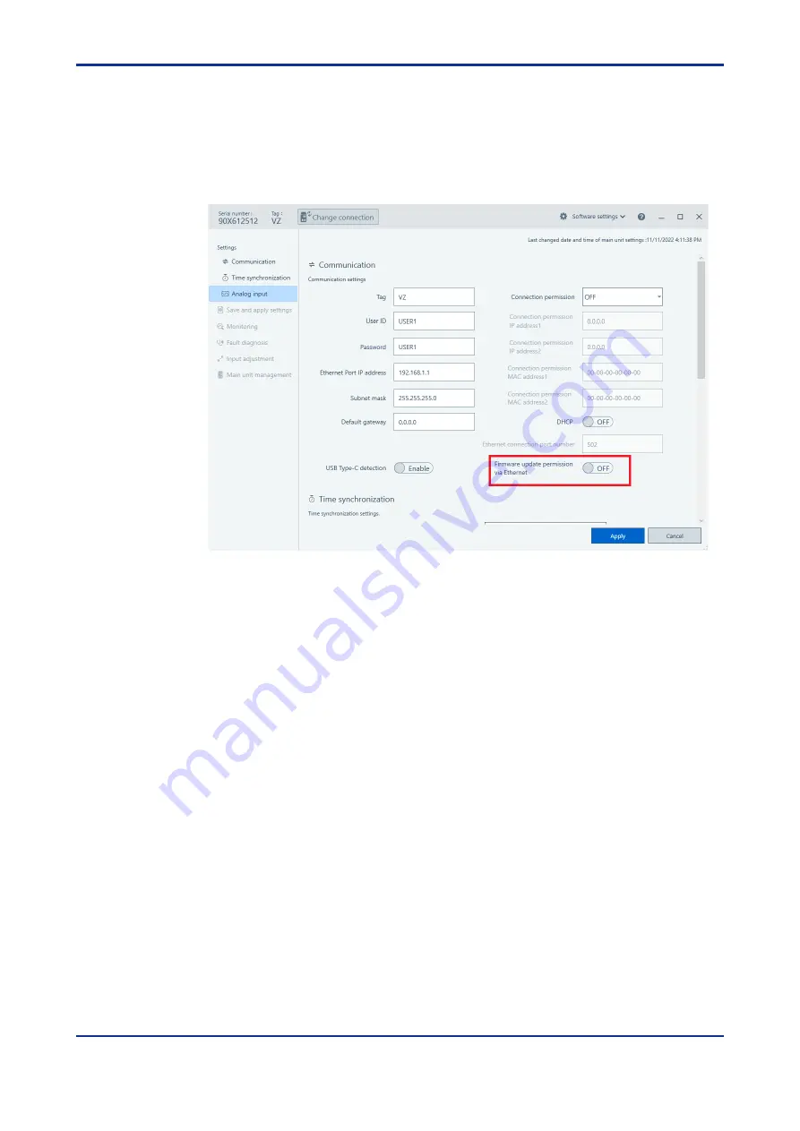
 Procedure for enabling firmware update from Ethernet 


Click Settings > Communication and the following screen appears. 
Click the [Edit mode] button 


Check the setting of the "Firmware update permission via Ethernet" parameter. 
Change the setting value to "ON" and click the [Apply] button. 
This writes the setting value to the VZ20X at the connection destination. 

 
This completes the operation. 


Summary of Contents for VZ20X

Page 1: ...User s Manual VZ20X Analog Sensing Unit User s Manual IM 77V01B01 01EN IM 77V01B01 01EN 5th Edition...

Page 2: ...fications can be downloaded from the following URL Adobe System s Adobe Acrobat Reader or later latest version recommended URL https www yokogawa com ns vz Electronic Manuals Name of Manual Manual No...

Page 3: ...tice as a result of continuing improvements to the instrument s performance and functions Every effort has been made in the preparation of this manual to ensure the accuracy of its contents However sh...

Page 4: ...01 and later QR Code The product has a QR Code pasted for efficient plant maintenance work and asset information management It enables confirming the specifications of purchased products and user s ma...

Page 5: ...tion Precautions Related to the Protection Safety and Alteration of the Product This instrument conforms to IEC safety standards IEC61010 1 and IEC61010 2 030 Overvoltage Category I 1 Measurement Cate...

Page 6: ...f the product is strictly prohibited This product is intended to be handled by skilled trained personnel for electric devices When mounted on a DIN rail attach the rail to a sufficiently strong steel...

Page 7: ...e wiring scraps chips or the like to enter inside the product This causes electric shock fire failure or malfunction Also note that wiring scraps and chips easily enter the product during wiring when...

Page 8: ...use discoloring or deformation Keep electrically charged objects away from the signal terminals Failure to do so may damage the product If there are any symptoms of trouble such as strange odors or sm...

Page 9: ...Pb Hg Cd Cr6 PBB PBDE GB T26572 GB T26572 SJ T11364 RoHS Some parts of this product include the restricted substances of RoHS Directive buttheir applications are under the exemption of the directive...

Page 10: ...r VZ20X style 2 01 and later Hardware Specifications Power Supply Specifications 24 VDC 10 15 4 5 W or less or USB power supply Rated Voltage input signal 60 VDC DC voltage 2 V range or higher and sta...

Page 11: ...ware and solely for your Licensee s internal operation use Use of the Software Product shall be subject to the terms and conditions of General Specifications in addition to this Agreement if any 2 2 U...

Page 12: ...RE PRODUCT OR THE RESULTS ARISING THEREFROM IS PRECISE RELIABLE OR UP TO DATE THAT THE SOFTWARE PRODUCT IS COMPATIBLE WITH ANY PARTICULAR SOFTWARE REQUIRED TO RUN THE SOFTWARE PRODUCT OR THAT THE SOFT...

Page 13: ...sputes controversies or differences which may arise between the parties hereto out of in relation to or in connection with this Agreement Dispute shall be brought exclusively in the Tokyo District Cou...

Page 14: ...nfigurator 5 6 5 3 3 Home Screen 5 7 5 4 Setup Guide 5 8 5 4 1 Making New VZ20X Settings and Changing VZ20X Settings 5 8 5 4 2 Changing Settings from the Configuration File 5 8 5 5 Connection Settings...

Page 15: ...nization of Input Sampling 7 8 7 1 12 RJC Reference Junction Compensation 7 8 7 1 13 ERJC External Reference Junction Compensation 7 8 7 2 Ethernet Communication 7 9 7 2 1 Outline 7 9 7 2 2 Connection...

Page 16: ...Contents 3 IM 77V01B01 01EN 5th Edition 2023 03 07 00 Revision Information 1...

Page 17: ...Contents 4 IM 77V01B01 01EN 5th Edition 2023 03 07 00 Blank Page...

Page 18: ...mming etc of the PC including GA10 Data Logging Software and PLC 1 2 System Configuration The following describes the system configuration of the VZ20X Ethernet communication The VZ20X can be used whe...

Page 19: ...n be used when connected to a host device such as PC PLC etc The VZ20X is connected to a PC by USB cable The parameter settings monitoring and input adjustment can be made by VZ Configurator The figur...

Page 20: ...the need to use a general purpose Ethernet hub When connected to the GA10 data can be acquired without the need to prepare a special program When connected to a PC PLC data can be acquired by creatin...

Page 21: ...f daisy chain connections 15 3 Power supply Connect by 24 VDC 4 USB Type C port Connect by USB cable Type C 5 Analog input status LED Lights flashes when the power is turned on and indicates the opera...

Page 22: ...up the device that will acquire the data Acquire the data using Modbus TCP Set up the data acquisition device Set up the VZ20X in VZ Configurator Programming Acquire data Step 2 Step 3 Step 4 Wire th...

Page 23: ...2 2 IM 77V01B01 01EN 5th Edition 2023 03 07 00 Blank Page...

Page 24: ...e changes suddenly This may also result in a measurement error when thermocouple input is measured In situations such as this allow the VZ20X to acclimatize to the surrounding environment for at least...

Page 25: ...ear heat sources can cause adverse effects on the internal circuitry Where an excessive amount of soot steam moisture dust or corrosive gases are present Soot steam moisture dust and corrosive gases w...

Page 26: ...ng a DIN rail in place screw the rail in at intervals of less than 100 mm This is required to ensure the strength of the rail For side by side close mounting remove the VZ20X from the DIN rail when co...

Page 27: ...ng sound The lever is secured at this position 2 In this state pull the VZ20X towards you and lift up its body to remove the VZ20X from the DIN rail DIN rail vertical mounting dimensions When using a...

Page 28: ...3 5 IM 77V01B01 01EN 5th Edition 2023 03 07 00 External dimensions Unit mm Third angle projection Normal tolerance value of JIS B 0401 2016 tolerance class IT18 2...

Page 29: ...3 6 IM 77V01B01 01EN 5th Edition 2023 03 07 00 Blank Page...

Page 30: ...lied to the input terminals install the product in a panel or a locked cabinet to prevent the input terminals from being touched To prevent fire use cables having a temperature rating of 80 C or more...

Page 31: ...being applied to terminals The product might become damaged if static electricity is applied to signal wires or transient noise is applied at a similar high voltage Take measures to prevent noise fro...

Page 32: ...B communication VZ20X side USB connector shape Type C Connection cable Use a USB cable of USB 2 0 or higher 3 If twin ferrule terminals are not used when the power supply is transition wired the cable...

Page 33: ...that wiring cannot be drawn out do not exert unnecessary force to draw out the wiring Rotate the cable to change the orientation of the ferrule terminal while pressing in the white release button usin...

Page 34: ...crimped onto the cable into the push in terminal With thin solid core wire wiring sometimes bends and cannot be connected simply by pushing it in In this case push the lead into the push in terminal b...

Page 35: ...esistance Terminal Layout Analog input channels Terminal No Voltage Standard signal Thermocouple 3 wire resistance temperature detector 4 wire resistance temperature detector 4 wire resistance 1 Use f...

Page 36: ...ere are no functional limitations on a Type C If not using Type C functionality and operation will vary depending on the firmware version and USB Type C detection setting If the firmware version is R1...

Page 37: ...e USB cable is connected or when removing the USB cable prevent a load from being placed on the USB connector in the front direction of the product When disconnecting the USB cable draw it out towards...

Page 38: ...progress Lit orange Data is being sent and received at 100 Mbps When used as a standalone unit Use port 1 When used in a daisy chain connection Connect the host device PC PLC side of the cable to port...

Page 39: ...4 10 IM 77V01B01 01EN 5th Edition 2023 03 07 00 The following shows an example of a daisy chain connection The following shows an example of a connection via an Ethernet hub...

Page 40: ...circuit breaker 1 to clearly indicate that it is a device for shutting off the power supply to the product 1 IEC60947 compliant product Use of a non specified electric wire may cause abnormal heating...

Page 41: ...Method 1 Turn the power supply source of the VZ20X off 2 Connect the power cable to the power supply terminal Power supply terminal layout No Function 1 24 VDC power supply 2 24 VDC power supply 3 Us...

Page 42: ...ement Operating environment Item Windows 11 1 Japanese English Windows 10 1 Japanese English Edition Pro Enterprise 64bit Pro Enterprise 64bit Version 1 21H2 or later 20H2 or later CPU Intel processor...

Page 43: ...of VZ Configurator For Windows 10 Check that VZ Configurator is registered by Start Apps Yokogawa Electric Corporation VZConfig in the Windows menu For Windows 11 Check that VZ Configurator is registe...

Page 44: ...Applying Settings 5 8 Managing Files 6 1 Monitoring 9 2 Trouble Notification Function 8 2 Input Adjustment 8 4 Firmware Update 8 3 Parameter Initialization Function Save and apply settings screen Read...

Page 45: ...Edition 2023 03 07 00 Screen hierarchy The following shows the hierarchy of the screens that expand from the home screen Screens can expand from the home screen to each respective item after connectio...

Page 46: ...nfigurator 5 2 1 Connecting the Hardware PC USB connection Connect the VZ20X to the PC by USB cable The connector on the VZ20X is a Type C connector PC Ethernet connection Connect the Ethernet cable f...

Page 47: ...ZConfig in the Windows menu on the PC to start up VZ Configurator Desktop shortcut Double click the VZ Configurator shortcut on the Windows desktop to start up VZ Configurator Configuration file Start...

Page 48: ...tion destination of the PC and VZ20X Connected device display The serial number of the VZ20X and tag names are displayed here When VZ Configurator is not connected to the VZ20X Disconnected is display...

Page 49: ...Z Configurator and make the settings for the VZ20X in the following sequence 1 Connection settings see 5 5 2 Editing from the settings screen see 5 6 1 3 Communication settings see 5 7 1 4 Time synchr...

Page 50: ...n button on the home screen and the Connection settings window is displayed After connecting the Change Connection button will be displayed In the Connection settings window click the Direct input tab...

Page 51: ...ng values of all parameters on the connected VZ20X are read and are then reflected in the setting display Search procedure for Ethernet communication 1 Click the New connection button on the home scre...

Page 52: ...the Connect button To return to the home screen without saving the connection settings click the Cancel button Enter the user ID and password and click the Connect button This determines the VZ20X to...

Page 53: ...disconnected after setting the parameters In an Ethernet connection Communication is disconnected when parameter setting values are changed In an USB connection Communication is disconnected when comm...

Page 54: ...e Edit mode and the setting values of each parameter can be changed After changing setting values click the Apply button Clicking the Cancel button while settings are being changing exits the Edit mod...

Page 55: ...ion After the new parameter setting values are written all parameters are read from the VZ20X at the connection destination If there is a difference between the parameters that were written back and t...

Page 56: ...he Edit mode and the setting values of each parameter can be changed After checking and editing parameter setting values click the Apply button To not apply setting values click the Cancel button The...

Page 57: ...ation Settings Set up communication with the VZ20X Communication setup procedure 1 In the operation list in the home screen click Communication Click the Edit mode button Also in the operation list in...

Page 58: ...synchronization Click the Edit mode button Also in the operation list in the home screen open the file to save at Select file from Save and apply settings 2 After inputting the setting values click t...

Page 59: ...st in the home screen click Analog input Click the Edit mode button Also in the operation list in the home screen open the file to save at Select file from Save and apply settings Select the desired c...

Page 60: ...e 5 8 1 Saving Settings File Procedure 1 Click Save and apply settings Save button The Save As window opens Files can be named and saved in this window 5 8 2 Loading Settings Files Procedure 1 Click S...

Page 61: ...nd password as they will be needed when connecting to the VZ20X Parameter name Setting range Default Explanation User ID Max 16 1 byte characters alphanumeric characters and symbols USER1 Sets the use...

Page 62: ...VZ20X to set the parameters to and click the Connect button The following screen is displayed 2 Enter the user ID and password already set to the VZ20X and click the Connect button 3 When the user ID...

Page 63: ...n 2023 03 07 00 5 10 Software Settings 5 10 1 Software Version Display the version of VZ Configurator Software version checking procedure 1 Click Software settings at the top of the screen The version...

Page 64: ...The display language on VZ Configurator can be switched between English and Japanese Display language switching procedure 1 At the top of the screen click Software settings Language and then select an...

Page 65: ...ader of Adobe Systems Incorporated You need to obtain and install it separately Use the latest version of User s Manual You can download the latest version of the User s Manual from the following webs...

Page 66: ...tags measured values and temperature unit 2 Show hide graph Checking this toggles graph display between show and hide Even when graph display is set to hide measurement values are displayed as digital...

Page 67: ...6 2 IM 77V01B01 01EN 5th Edition 2023 03 07 00 Monitoring procedure 1 Click Operation list Monitoring and the following screen appears Select the display channel to monitor...

Page 68: ...esistance thermocouple and resistance temperature detector can be measured Signals input to the VZ20X are sampled at a sampling period of 1 ms and undergo A D conversion and various input operations t...

Page 69: ...V 6 V 6 000 6 000 V 20 V 20 000 20 000 V 60 V 60 00 60 00 V Standard signal 0 4 to 2 V 0 4000 2 0000 V 1 to 5 V 1 0000 5 0000 V 4 wire resistance 200 4 wire 0 00 200 00 2000 4 wire 0 0 2000 0 Thermoc...

Page 70: ...upper limit value of each input type in the input type table This sets the maximum value to be used in scaling calculation Min value of input scale 99999 to 99999 Min value of input scale Max value of...

Page 71: ...OFF UP DOWN UP This parameter is for setting burnout detection 7 1 6 Data Acquisition Interval Analog inputs are sampled at a sampling period of 1 ms However the data acquisition interval can be chang...

Page 72: ...moval setting 50 Hz 60 Hz COMMON 50 Hz Set the power frequency noise removal filter 50 Hz Filters out 50 Hz noise 60 Hz Filters out 60 Hz noise COMMON Filters out noise both 50 Hz and 60 Hz When the m...

Page 73: ...oving average cycles immediately after calculation is started the average of the currently acquired data is calculated When measured values are in error range over burnout A D error the moving average...

Page 74: ...re in error range over burnout A D error the data of those measured values is removed from the filter calculation The table below shows the relationship between the filter coefficient and filter time...

Page 75: ...function is enabled with firmware version R1 02 01 or later If thermocouple input is selected RJC can be turned OFF ON Normally input compensation is performed using the VZ20X RJC function However th...

Page 76: ...and monitoring can be performed on VZ Configurator Note Stop data acquisition before changing settings Monitoring can be carried out during data acquisition Communication specifications Item Specifica...

Page 77: ...ss sometimes changes and data can no longer be acquired The Ethernet keepalive judgment time is set to 25 seconds The DHCP client function is not supported in lease extension requests For this reason...

Page 78: ...ss 1 Connection permission IP address2 0 0 0 0 to 255 255 255 255 0 0 0 0 Sets the connection permission IP address 2 Connection permission MAC address1 00 00 00 00 00 00 to FF FF FF FF FF FF 00 00 00...

Page 79: ...ssing from only registered IP addresses or MAC addresses and for blocking accessing from non registered IP addresses and MAC addresses This function prevents unauthorized accessing and heightens secur...

Page 80: ...ximum of 120 channels at the same A D conversion timing Parameter Name Setting Range Default Explanation Connection type 1 unit Master unit of daisy chain Relay unit of daisy chain Terminal unit of da...

Page 81: ...ication after the VZ20X is started up Write the time also when the power supply is turned off midway At writing of the time the time stamp is omitted or set in duplicate Device targeted for writing of...

Page 82: ...ynchronization is performed The master is one VZ20X unit in the daisy chain connection Connection with a host device such as PC PLC etc VZ20X relay unit of daisy chain or terminal unit of daisy chain...

Page 83: ...2 as it does not function on 1 unit or on the terminal unit in a daisy chain connection Connection example 1 unit Connection example multiple units When increasing the number of connected units incre...

Page 84: ...t 2 Port 2 Port 2 PC or PLC etc Master Relay Relay Terminal Unusable Unusable Connection type Master Relay Relay Terminal Connection type Time synchronization supported in a daisy chain Time synchroni...

Page 85: ...01 00 00 00 000 At writing of the time the time stamp is omitted or set in duplicate In a daisy chain connection set the date and time to the master unit of the daisy chain VZ20X from the PC PLC In t...

Page 86: ...t possible when writing to a register other than a register number given in this table is performed 1 Register number Reference no 2 Hex number hexadecimal Register name 3 R W 40001 0000 VZ20X time se...

Page 87: ...te and time operate from the value written to the VZ20X time setting register At startup or when the time has not been set the date and time operate from 1970 01 01 00 00 00 000 40006 0005 R 40007 000...

Page 88: ...rence 123 2 Convert the differences to milliseconds Before conversion Conversion formula Result of conversion calculation Day difference 18828 18828 24 60 60 1000 1626739200000 Hour difference 12 12 6...

Page 89: ...W Descriptions 40101 0064 Measured value time stamp R The time of measured values can be read This setting is common to all channels The coordinated universal time or UTC can be read as a 64 bit unsig...

Page 90: ...lue 40166 00A5 R 40167 00A6 CH4 measured value status R Same as CH1 measured value status 40168 00A7 CH5 measured value R Same as CH1 measured value 40169 00A8 R 40170 00A9 CH5 measured value status R...

Page 91: ...2 overscale 5 0 of input range 3 Input type OFF data 0 6 No data 0 7 Not fixed data during range changing 0 8 burnout error 105 0 of input range 9 burnout error 5 0 of input range 10 ADC error 0 16 T...

Page 92: ...address setting 2 R W 41103 044E IP address setting 3 R W 41104 044F IP address setting 4 R W 41105 0450 Subnet mask setting 1 R W 0 to 255 Subnet mask setting 1 Subnet mask setting 2 Subnet mask sett...

Page 93: ...ress 1 setting 2 R W 41133 046C Connection permission MAC address 1 setting 3 R W 41134 046D Connection permission MAC address 1 setting 4 R W 41135 046E Connection permission MAC address 1 setting 5...

Page 94: ...55 Connection permission IP address 2 used 1 Connection permission IP address 2 used 2 Connection permission IP address 2 used 3 Connection permission IP address 2 used 4 41227 04CA Connection permiss...

Page 95: ...used continued Register number Reference no Hex number hexadecimal Register name R W Descriptions 41251 04E2 DHCP setting used R 0 OFF 1 ON 41252 04E3 Connection type setting used R 0 1 unit 1 Master...

Page 96: ...log input setting parameters channel 1 CH1 Register number Reference no Hex number hexadecimal Register name R W Descriptions 41501 05DC CH1 tag R W Set using UTF16 41502 05DD R W 41503 05DE R W 41504...

Page 97: ...W 99999 to 99999 41526 05F5 41527 05F6 CH1 input scale decimal point position R W 0 to 4 41528 05F7 CH1 burnout detection R W 0 OFF 1 UP 2 DOWN 41529 05F8 CH1 power supply frequency noise removal filt...

Page 98: ...554 0611 41604 0643 41555 0612 41605 0644 41556 0613 41606 0645 41557 0614 41607 0646 41558 0615 41608 0647 41559 0616 41609 0648 41560 0617 41610 0649 41561 0618 41611 064A 41562 0619 41612 064B 4156...

Page 99: ...41709 06AC 41660 067B 41710 06AD 41661 067C 41711 06AE 41662 067D 41712 06AF 41663 067E 41713 06B0 41664 067F 41714 06B1 41665 0680 41715 06B2 41666 0681 41716 06B3 41667 0682 41717 06B4 41668 0683 41...

Page 100: ...41809 0710 41760 06DF 41810 0711 41761 06E0 41811 0712 41762 06E1 41812 0713 41763 06E2 41813 0714 41764 06E3 41814 0715 41765 06E4 41815 0716 41766 06E5 41816 0717 41767 06E6 41817 0718 41768 06E7 41...

Page 101: ...861 0744 41862 0745 41863 0746 41864 0747 41865 0748 41866 0749 41867 074A 41868 074B 41869 074C 41870 074D 41871 074E 41872 074F 41873 0750 41874 0751 41875 0752 41876 0753 41877 0754 41878 0755 4187...

Page 102: ...d and write registers on the VZ20X and exchange data between connected devices The VZ20X can be connected to IEEE802 3 compatible networks by a 100BASE TX Ethernet connection Host device PC etc Applic...

Page 103: ...0 seconds or more from the host device after a connection is established VZ20X breaks the connection The max number of transactions on VZ20X is 1 When sending commands continuously check the response...

Page 104: ...es the following seven bytes Byte No 0 1 2 3 4 5 6 Description Transfer ID Protocol ID Number of bytes Unit ID Transfer ID Specify any value for identifying transactions on the host device The VZ20X r...

Page 105: ...when an error occurs refer to the response error code Request during normal operation Read n items of data MBAP Header PDU Number of bytes 2 2 2 1 1 2 2 Command elements Transfer ID Protocol ID Numbe...

Page 106: ...on code Response error code Error Code Meaning Cause 01 Function code error The function code does not exist 02 Register No error A No out of range was specified 03 Number of registers error A number...

Page 107: ...ster No The maximum number of registers that can be read in a single operation is 100 For details on the response format when an error occurs refer to the response configuration Message during normal...

Page 108: ...r setting range is set a normal response is returned though data is not written Message during normal operation Element MBAP Header PDU Number of bytes 2 2 2 1 1 2 2 Command elements Transfer ID Proto...

Page 109: ...h data is not written Message during normal operation Element MBAP Header PDU Number of bytes 2 2 2 1 1 2 2 Command elements Transfer ID Protocol ID Number of bytes Unit ID Function code 0x10 Register...

Page 110: ...lement MBAP Header PDU Number of bytes 2 2 2 1 1 2 Command elements Transfer ID Protocol ID Number of bytes Unit ID Function code 0x46 Function selection Hex Arbitrary 0000 0004 01 46 0001 or 0002 Res...

Page 111: ...ion time Data acquisition interval Data retention time 1 ms 2 s 10 ms 20 s 50 ms 100 s 100 ms 200 s Start End YES YES YES Not yet buffered Data omission Data acquisition normal NO NO NO Function code...

Page 112: ...whichever function selection code is set Data acquisition error status Error Code Description 00 No error 01 Buffer is not full 02 Data omission occurred CHn STS n 1 to 8 This is the measured value s...

Page 113: ...8th to 15th bits are 0 UNIT status Code Descriptions 0x0000 No error 0x2000 Parameter error 0x0100 System error 0x0200 Memory device FRAM error 0x0400 Input hardware no response Message during normal...

Page 114: ...CH8 Data1 CH1 STS1 CH2 STS1 CH3 STS1 CH4 STS1 CH5 STS1 CH6 STS1 CH7 STS1 CH8 STS1 year month day 2 time 2 UNIT status Data Measured value Measured values are time stamped The format of the time stamp...

Page 115: ...VZ20X has a USB port exclusively for VZ Configurator VZ20X parameter settings can be setup up or monitoring can be performed using VZ Configurator 7 3 1 Specification The PC uses the Windows standard...

Page 116: ...Periodically inspect the operating status of the VZ20X to make sure that it is being used in a good condition at all times Check to see if LED displays analog inputs and communication are being perfo...

Page 117: ...1 Wire the VZ20X to the calibration equipment as shown in the figure on the next page and sufficiently warm up each of the equipment Warm up the VZ20X for at least 40 minutes For precautions in wirin...

Page 118: ...utput VZ20X input terminal HI LO 1 2 3 4 A B b Reistor Output VZ20X input terminal Ensure that the resistance of 3 conductors is the same value HI LO 1 2 3 4 a A B b Resistor Output VZ20X input termin...

Page 119: ...n instance where the temperature of the probe is 0 C the temperature of the input terminal is indicated as the measured value When calibrating the VZ20X input obtained by subtracting this compensation...

Page 120: ...the VZ20X off Doing so might cause the VZ20X to no longer operate normally Note To enter the input adjustment mode click the Execute Adjustment button in the input adjustment screen at the operation...

Page 121: ...Standard signal 0 4 2V 6 V DC voltage 6V Standard signal 1 5V 20 V DC voltage 20V 60 V DC voltage 60V 200 3 wire Resistance temperature detector Pt100 H 3 wire 400 3 wire Resistance temperature detect...

Page 122: ...ting environment conditions are within specification 23 2 C 55 10 RH Zero point adjustment Full point adjustment 1 2 3 4 VZ20X input terminal 1 2 3 4 DC voltage generator DC V Output VZ20X input termi...

Page 123: ...nnect to the target VZ20X Click the Input adjustment button in the operation list 4 Select the channel on which to perform input adjustment Click the Execute Adjustment button for the range to be adju...

Page 124: ...llowing dialog is displayed 7 Connect the calibration equipment to the channel for the analog input to adjust Input the reference value for the range to be adjusted according to the table below and cl...

Page 125: ...01EN 5th Edition 2023 03 07 00 8 When full point adjustment is completed the following dialog is displayed To return to the input adjustment screen without saving the adjustment results click the Disc...

Page 126: ...tton This writes the adjustment values to the VZ20X 10 Repeat steps 5 to 9 for each individual range to be adjusted 11 To adjust another channel select the channel to be adjusted and repeat steps 5 to...

Page 127: ...sometimes displayed The following table summarizes a list of error codes Error Code Description Corrective action 001 Input error Input is not correct Check the input type 002 Outside adjustment value...

Page 128: ...configuration file as necessary If the VZ20X is turned off or communication is interrupted during initialization of parameters initialization is not performed successfully Initialization must be exec...

Page 129: ...8 14 IM 77V01B01 01EN 5th Edition 2023 03 07 00 Initialization procedure 1 Click Main unit management Reset tab and the following screen appears Click the Reset button...

Page 130: ...1B01 01EN 5th Edition 2023 03 07 00 2 This starts parameter initialization When parameter initialization is completed the following screen appears 3 Click the OK button VZ20X reboots This completes th...

Page 131: ...form other operations Please use VZ Configurator R1 01 02 or later when updating the firmware Do not update the modified firmware file to VZ20X If done the operation of VZ20X is not guaranteed The fir...

Page 132: ...ngs Communication and the following screen appears Click the Edit mode button 2 Check the setting of the Firmware update permission via Ethernet parameter Change the setting value to ON and click the...

Page 133: ...M 77V01B01 01EN 5th Edition 2023 03 07 00 Firmware update procedure Common to Ethernet and USB 1 Click Main unit management Firmware Update tab and the following screen appears Click the Select file b...

Page 134: ...ompleted the following screen appears The LED on the unit changes as follows During firmware update Flashing green or flashing alternately green blue Completion of firmware update Lights blue after th...

Page 135: ...07 00 Checking the firmware version Check to see if the firmware has been successfully updated 1 Begin operations by establishing a new connection with the VZ20X 2 Click Main unit management Firmware...

Page 136: ...ce error Normal operation Not fixed Not fixed Failure Ask for repair At power supply on During operation Flashes red Lights out at abnormal input channel Lights green at normal input Display not possi...

Page 137: ...le 105 Down scale 5 Normal operation Normal operation Check wiring and sensors When values become normal the LED display state returns to lit green state During operation Lights green Flashes green OV...

Page 138: ...Configurator via Ethernet or USB communication Click Fault diagnosis and the following screen that displays the error details appears Fault diagnosis information shows the date and time status and cor...

Page 139: ...s red Service is required Contact your nearest YOKOGAWA dealer Flashes green Parameters have been initialized Set communication parameters again Lights blue At power supply on the time has not been se...

Page 140: ...ly NO YES Set IP address correctly Consult your network administrator YES NO NO YES Ethernet communication is not possible Wire correctly Is Ethernet wiring correctly wired Is power being supplied cor...

Page 141: ...aveform swings to either 0 side or 100 side Correct range setting Wire correctly Install terminal block correctly Is input wiring correctly wired NO YES Does input satisfy specifications Is range sett...

Page 142: ...e VZ Configurator to change the DHCP function setting to OFF via a USB connection When the setting is ON the IP address sometimes changes and communication is no longer possible Use ping to check the...

Page 143: ...d After writing parameters re connect by beginning with a new connection before reading the parameters on the unit Then connect the other VZ20X and execute reading of parameters Q6 Is it possible to c...

Page 144: ...mal operation In an Ethernet connection Communication is disconnected when parameter setting values are changed Begin with a new connection In an USB connection Communication is disconnected when comm...

Page 145: ...9 10 IM 77V01B01 01EN 5th Edition 2023 03 07 00 Blank Page...

Page 146: ...ion permission IP address 1 Connection permission IP address2 1 0 0 0 0 to 255 255 255 255 0 0 0 0 Sets the connection permission IP address 2 Connection permission MAC address1 1 00 00 00 00 00 00 to...

Page 147: ...the input type table This sets the minimum measurement value of the input Max value of input scale 99999 to 99999 Min value of input scale Max value of input scale Min value of input scale 1 digit to...

Page 148: ...sing Modbus TCP function codes 03 and 16 Bias The default follows each input type in the input type table 99999 range 0 The decimal point position follows the decimal point position set for scaling or...

Page 149: ...App 4 IM 77V01B01 01EN 5th Edition 2023 03 07 00 Blank Page...

Page 150: ...on example Time synchronization supported in this configuration daisy chain connection excluding when Connection type is 1 unit Time synchronization not supported in this configuration Input Functions...

Page 151: ...n speed 100 Mbps status Number of LEDs 2 per port LED display color Green orange Main unit status LED Lights green when the power is turned on and indicates the operating status of the VZ20X Number of...

Page 152: ...l 10 M or more other than DC voltage 2 V range or higher and standard signal Allowable signal source resistance 2 k or less DC voltage 2 V range or higher and standard signal 250 or less DC voltage 1...

Page 153: ...0 C 0 8 C 0 to 500 C 0 4 C 500 to 1370 C 0 7 C 270 to 200 C Accuracy not guaranteed 200 to 0 C 1 6 C 0 to 500 C 0 8 C 500 to 1370 C 1 4 C E 270 0 to 800 0 C 270 to 200 C Accuracy not guaranteed 200 t...

Page 154: ...C desktop installation 10 to 50 C Ambient humidity 5 to 90 RH condensation not allowed Operating environment Sites not subjected to hydrogen sulfide and other corrosive gases or dust and sites not sub...

Page 155: ...H8 Terminal No DC voltage standard signal Thermocouple 3 wire resistance temperature detector 4 wire resistance temperature detector 4 wire resistance 1 Use forbidden Use forbidden Use forbidden a 2 U...

Page 156: ...lay compatible with OS Display compatible with OS Communication port USB port Ethernet port 100Base TX For the details refer to the communication specifications USB port Ethernet port 100Base TX For t...

Page 157: ...Monitoring Yes Yes No Yes Fault diagnostics Yes Yes Yes Yes Input adjustment Yes Yes No Yes Firmware update Yes Yes No Yes Parameter initialization Yes Yes Yes Yes Basic Conditions and Individual Con...

Page 158: ...2022 3rd Edition CE UKCA safety and EMC standards compliant Nov 11 2022 4th Edition CSA UL safety standard compliant March 7 2023 5th Edition Functionality improved when power supplied over USB regist...

Reviews: