YOKOGAWA TM20 User Manual Download Page 80

71

IM 54011-E

71

71

Measuring

T

emperatures

4

Measuring Temperatures of Channels A and B Simultaneously

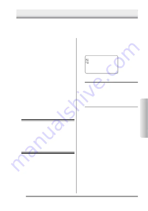
 Selecting input channels

Using the [CH] key to select two channels.

The channel indications below “INPUT” changes ac-
cordingly.

Burger

56.7

°

C

[TIP]

When data recorded by single-channel mea-
surements remains in the selected tag or log,
you cannot choose channels A and B at the same
time.  Or when data recorded by two-channel
measurements remains in the selected tag or
log, you cannot choose channel A, B, or D.
Delete the recorded data in either case.

For a selected tag or log, the measured values of channels A and B can be re-
corded simultaneously.  However, if data recorded by single-channel measure-
ments remains in the selected tag or log, simultaneous two-channel recording
cannot be started.  In this case, first delete the data from the record.

See Also

• For how to delete measured data, refer to

the following sections in the “Before Use”
part:

-

Section 5.3, “Clearing the measurement
data associated with the tag”

-

Section 5.7, “Clearing the measurement
data associated with the log”

• For basic operations of temperature mea-

surements, refer to the following chapters
in the “Measuring Temperatures” part:

-

Chapter 2, “Measuring Temperatures
with the Collector Function”

-

Chapter 3, “Measuring Temperatures
with the Logging Function”

Plugging in probes

Plug probe cables into input channels A and
B.

 Note

Use a non-grounded probe for either
channel.  If there is no choice other than
to use grounded probes for both chan-
nels, ensure that the potential difference
between the channels A and B will not
exceed 

±

1 V.  Nevertheless, when per-

forming real-time upload of measured
values, non-grounded probes must be
used for both channels.

4 Measuring Temperatures of Channels A and B Simultaneously

Summary of Contents for TM20

Page 1: ...User s Manual IM 54011 E 2nd Edition 540 11 TM20 Thermo Collector ...

Page 2: ...ures Read this part when measuring temperatures This part explains major operations required to actually measure temperatures Working with Measured Data Read this part when using and analyzing the data measured by a TM20 This part explains how to transfer the measured data to a personal computer and print them Checking contents of package When a TM20 Thermo Collector is delivered visually check it...

Page 3: ...ce the product Handling precautions Only parts and consumables specified by Yokogawa M C should be used in the product Do not store the product in a location where it will be exposed to direct sunlight or high temperatures otherwise it may be discolored or deformed Warnings cautions and notes Follow the safety instructions in this manual when handling a TM20 or its connected acces sories Yokogawa ...

Page 4: ...sure that the potential differences between probes do not exceed 1 V Do not use a worn or damaged probe which may be incapable of correct tempera ture measurements Before removing a probe from the TM20 pull the probe away from the object mea sured When using a probe for liquids such as a needle probe insert it into the liquid to be measured by approximately half the dimension of the probe s stylus...

Page 5: ...ns in this manual may not precisely depict the actual product or software Care of product If there is a need to clean the casing wipe the surfaces with a wrung wet cloth To remove tough stains use a cloth dampened with a diluted neutral detergent Do not use any solvent other detergent or chemical other than neutral detergents to prevent the prod uct from being damaged Keep the connectors and other...

Page 6: ...ering characters 7 Entering lowercase characters 7 Preparing for Measurement 1 Overview of Preparation for Measurement 8 2 Setting Up the Main Unit 9 2 1 Setting the date and time 9 2 2 Setting the name of the main unit 10 3 Setting Up with the Personal Computer 11 3 1 Setting up the Thermo Collector software 11 Connecting the personal computer and the main unit 11 Installing the Thermo Collector ...

Page 7: ...ngs 45 4 Setting Up with the Main Unit 46 4 1 Setups required to use collector function setting tag names alarms name of person and comment and selecting input channel s 46 Setup contents 46 Creating a new tag 46 Setting the alarm function for each tag 47 Batch setting the alarm function 49 Registering the measurement operator name 50 Setting comments 51 4 2 Setups required to use the logging func...

Page 8: ...0 To start a measurement in the logging mode at a specified time timer function 80 To quickly search for a tag or log 82 To record measured data if the tag or log has not been set 82 To record the start time and finish time of an operation only with the collector function 83 To restrict inputs from the panel keys the key lock function 83 To enable only the panel keys yellow keys requied for mesure...

Page 9: ... the Printer 91 2 1 Output preparation 91 Printer main unit connection 91 Confirming the printer setup conditions 92 2 2 Outputting the measured data to the printer 93 APPENDIX Thermo collector specifications 96 Operation environment of Thermo Collector software 99 External view and dimensions 99 Using the waterproof case Model 93011 coming with TM20 100 Function keys quick reference 101 ...

Page 10: ...00 00 56 0 C 00002 99 10 08 18 00 10 57 5 C 00003 99 10 08 18 00 25 58 5 C 00004 99 10 08 18 00 35 59 8 C 00005 99 10 08 18 00 45 61 2 C 00006 99 10 08 19 00 00 62 0 C 00007 99 10 08 19 00 11 62 0 C 00008 99 10 08 19 00 26 70 0 C 00009 99 10 08 19 00 34 75 0 C 00010 99 10 08 19 00 47 81 0 C OK OK OK OK OK OK OK OK OK NG Lo Person Smith Smith Smith Smith Smith Smith Smith Smith Smith Smith NG NG NG...

Page 11: ...9 20 00 40 10 5 C 00006 99 10 09 20 00 50 11 0 C 00007 99 10 09 20 01 00 10 5 C 00008 99 10 09 20 01 10 10 5 C 00009 99 10 09 20 01 20 11 0 C 00010 99 10 09 20 01 30 10 5 C Printout of image from a recommended printer Log name Date and time Temperature Measurement interval It is possible to use maximum 10 logs and in these 10 logs a total of 20 000 pieces of data can be recorded However the more t...

Page 12: ...han nels A B and D Channel D is for a non contact thermo probe 6 ESC key Used to cancel the previous operation and return to the previous screen 7 Memory key Used to commence a temperature measurement with either the collector function or the logging function 8 key Used to select an appropriate tag log or function 9 LOGGING key Used to switch between the collector and logging functions Also used t...

Page 13: ...ged if the batteries are installed incorrectly 3 Close the battery compartment cover End of procedure Caution Remove old batteries from the compartment Battery liquid leakage may cause the main unit to malfunction or may damage it A BatteryEmpty message will appear on the LCD shortly before the battery life expires When this message appears replace the batteries Note Whenever replacing batteries b...

Page 14: ...he POWER key The time display screen appears on the LCD 19 13 15 The power of the main unit is turned on Turn the power supply to OFF Hold down the POWER key for about three seconds The power to the main unit will be shut down after a short beep has been sounded 4 Turn ON OFF of the Power Supply ...

Page 15: ...ll the keys are disabled In the FUNC lock state only the temperature mea surement keys can be used See Also For information about canceling the lock state refer to Chapter 7 Other Useful Functions in the Measuring Temperatures part 8 Indicates that the battery is almost used up Replace the battery as soon as possible after this symbol is displayed 9 Indicates that the instrument is set so that the...

Page 16: ... used to enter alphabets For example the key can be used to enter A to C and 2 To enter C press the 2 key three times To enter 2 press the key four times Key Mode 1 Alphanumeric input mode 1 A B C 2 ABC 2 DEF GHI JKL MNO PQRS TUV WXYZ Symbol 3 4 5 6 7 8 9 0 D E F 3 G H I 4 J K L 5 M N O 6 P Q R S 7 9 T U V 8 W X Y Z 0 Entering lowercase characters 1 Enter a character to be made small A N e w T a g...

Page 17: ...re the temperature Setting up TM20 via TM20 s faceplate Setting up TM20 from PC Setup to be performed in this part Make settings using a tag log table for Collector function such as the tag names input channel s used alarms name of the operator and comments Logging function such as the log name input channel s used measurement interval and measurement period Make settings for Collector function su...

Page 18: ...sed from this screen 1 Press the FUNC 6 and 1 keys in order The ClockSet screen appears on the LCD F61 ClockSet 2 Press the SET key A screen for setting the date appears Date 9 8 1 1 1 1 3 Enter the date Use the 0 to 9 keys for input The or key moves the cursor 4 Press the SET key A screen for setting the time appears Time 1 8 5 6 1 4 5 Enter the time 6 Press the SET key The specified time is set ...

Page 19: ... 9 C 1 Press the FUNC 9 and 7 keys in order The Name screen appears F97 Name 2 Press the SET key DevName Name00 3 Enter the name of the instrument Ex ample NO1 DevNamee NO1 See Also For how to enter letters and numbers refer to Chapter 6 How to Input Characters in the Before Use part 4 Press the SET key The instrument name is set The Name screen is restored F97 Name Press the ESC key repeatedly to...

Page 20: ...the personal computer and the main unit Purchase an RS 232C cable Model name 910 09 round DIN 8 pin to D sub 25 pin type Follow the procedure below to connect the main unit to the personal computer 1 Turn off the power to both the personal computer and main unit 2 Connect the personal computer and the main unit as shown in the following diagram D Bottom of the main unit 8 pin Main unit Personal co...

Page 21: ...are required for this installation 1 Place a floppy diskette Setup Disk 1 in the floppy disk drive of the personal com puter 2 Double click on the My Computer icon The My Computer folder is displayed 3 Double click on the floppy disk drive icon A drive in the case of a DOS V machine 4 Double click on Setup The Setup is initiated and a screen prompting the insertion of the second floppy diskette Se...

Page 22: ...of the third floppy diskette Setup Disk 3 appears 8 After inserting the third floppy diskette Setup Disk 3 click on the OK button TIP Do as follows to change the application install destination 1 Click on the Change Directory button 2 Select a installation destination folder 3 Click on the OK button After installation has been completed the following confirmation window is displayed TIP If the ano...

Page 23: ...2 Select Properties from the Comm menu The Properties window is displayed 3 Confirm that the settings are exactly as shown in the above figure If any of the settings are different set them to the values given below Setup item Setting value CommPort 1 Baud Rate 9600 Parity None Data Bits 8 Stop Bits 2 TIP The communication port setting values vary depending on the type of personal computer For more...

Page 24: ...setting the baud rate appears The dis played baud rate is 9600 bps which is factory set ting Baudrate 9600 3 Press the SET key A screen for setting the parity appears The displayed parity is None which is factory setting Parity None 4 Press the SET key A screen for setting the data length appears Con firm that the displayed data length is as shown in the following figure Data Len 8 b i t 5 Press t...

Page 25: ...lied software Initiating Thermo Collector software 1 Select Thermo Collector in the Programs accessed from the Start menu At first the model of the Thermo Collector selection screen is displayed 2 Click the text box to select the model TM20 3 Click on the OK button After the main screen of the software is displayed the Setup Tags Logs New screen is displayed ...

Page 26: ...o Collector software Select Exit from the File menu Saving the setup data in a file 1 Select Save As in the Setup Tags Logs menu accessed from the File menu The Save As window is displayed 2 Enter a file name in the File name field then click on the Save button The setup data is saved End of procedure ...

Page 27: ...p data 1 Select Open in the Setup Tags Logs menu accessed from the File menu The Open window is displayed 2 Select a file to be loaded then click on the Open button The specified file containing the setup data is loaded and the tag and log setup data in the file is displayed End of procedure ...

Page 28: ...ator data is saved in a file different from that in which the tag and log data is stored 1 Select Save As in the Setup Persons menu accessed from the File menu The Save as window is displayed 2 Enter a file name in the File name field then click on the Save button The measurement operator name data being set is saved End of procedure ...

Page 29: ...t operator name file 1 Select Open in the Setup Persons menu accessed from the File menu The Open window is displayed 2 Select a file to be loaded then click on the Open button The measurement operator name file is loaded and a list of operator names is displayed End of procedure ...

Page 30: ...a new file for setting up operator names New Open Save Save As Close Send Print Opens a file in which operator names have been stored Overwrites a file in which operator names have been set Saves a file in which operator names have been set under a new file name Closes the operator name setup screen Transmits the operator name data file currently opened to the main unit Setup Comment submenu Outpu...

Page 31: ...ive full names Clear Reference Table Clears the selection of reference tag log table Forward to Tag Log Setup File Forwards the settings in the open tag log table to the setup file Save As Saves the open tag log table under a new filename Person Table submenu New Opens a new blank person table a list of operators Open Opens an existing person table Save Saves the changes to the open person table S...

Page 32: ...etup file Save As Saves the open comment table under a new filename Voltage Range Settings submenu New Opens a new blank voltage setting file Open Opens an existing voltage setting file Save Saves the changes to the open voltage setting file Send Sends downloads the settings in the open voltage setting file to the TM20 Receive Receives uploads the voltage measurement settings inside the TM20 Save ...

Page 33: ...tag log table person table and comment table Performs data sorting in the columns of Abbr Name and Full name Mark usable only in tag log table person table and comment table Selects Select All or Cancel All of the selected settings high lighted in yellow for transmitting to the setting file etc TIP Measurement data received from the main unit cannot be edited using the Edit menu functions Display ...

Page 34: ...ed This function is the same as Open in the Setup Comments submenu of the File menu Save the comment file so it overwrites the existing file This function is the same as Save in the Setup Comments submenu of the File menu Transmits the comment data currently dis played on the screen to the main unit This function is the same as Send in the Setup Comments submenu of the File menu Loads the measured...

Page 35: ...tings as lists of the respective settings By simply choosing an entry from each table you can create a setup file for your TM20 Setup files person settings and comment setting Files containing settings to be written downloaded to a TM20 Tables of settings for creating setup files Each table contains settings required for measurement Abbreviated tag and log names can be replaced with the respective...

Page 36: ...mo Collector has multiple input channels and probes for measuring temperatures of substances in a vapor solid or liquid phase Since the probe to be used depends on the measuring object it is necessary to set the available input channel on a tag in advance The following table shows the probe types and their corresponding input channels Probe type Input channel Thermocouple types K J E and T 100 mV ...

Page 37: ...function can be inverted Specifically if this inverse alarm functions is set to ON an alarm will sound if the temperature falls below the upper limit or if the temperature rises above the lower limit Temperature Upper limit alarm 70 C Lower limit alarm 50 C 70 C 50 C Upper limit alarm 70 C Lower limit alarm 50 C Temperature 70 C 50 C Range in which the alarm sounds If OFF If ON TIP The alarm can a...

Page 38: ...tup Tag Logs New opens in it 2 From the File menu choose Tag Log Table then New to open the Tag Log Table window a document window Tag Log Table window 3 Enter the tag names in the Abbr Name column with a maximum of eight alphanumeric characters for example Burger 4 In the Full Name column enter more descriptive tag names There is no limitation in length with full names If you select this table as...

Page 39: ...fied channel is set 7 Click in the Upper Limit column The cursor moves to a cell for the Upper Limit 8 Enter the Upper Limit with numeric characters Example 150 0 TIP Enter a value that does not exceed Upper Limit of the probe used for actual measurement The Upper Limit that can be measured varies according to the probe used for measurement The specified upper limit temperature has been set ...

Page 40: ... setting is made and the cursor moves to the Lower Limit column 12 Enter the Lower Limit with numeric characters Example 135 0 TIP Enter a value that does not fall below the Lower Limit of the probe used for the actual measurement The Lower Limit that can be measured varies according to the probe used for the measurement The specified lower limit temperature has been set 13 Double click in the Lo ...

Page 41: ...own menu appears 16 Select either ON or OFF The alarm condition is set You can insert and add rows by either of the following ways Using a shortcut menu that opens by a right click Using keystrokes of CTRL I and CTRL R Repeat steps 3 16 to set as many tags as necessary 17 Save the table From the File menu choose Tag Log Table then Save As to save the table End of procedure ...

Page 42: ...s then New to open the Setup Tags Logs window of a blank setup file 3 Click The selected tag setting is then copied to the Setup Tags Logs window Tag log table Setup file 4 Select the measurement range The measurement range is selected as K meaning thermocouple type K by default To set to a different range click Channel A or Channel B box as appropriate in the Setup Tags Logs window and choose the...

Page 43: ... of the received data If a matching name is found Thermo Collector fetches the full name corresponding to the abbreviated name from the reference table and stores the full name in the Excel worksheet file in place of the abbreviated name 1 From the File menu choose Tag Log Table then Select Reference Table Then select the reference table in the dialog box that appears 2 Click Yes to confirm the se...

Page 44: ... to 8 alphanumeric characters that can be displayed on the TM20 screen 3 In the Full Name column enter the longer more descriptive names of the operator Full names have no limitation in length If you select this table as the reference person table Thermo Collector will replace the abbreviated names with the corresponding full names based on this table when receiving measured data from a TM20 4 Add...

Page 45: ...l names 1 From the File menu choose Person Table then Select Reference Table Then select the reference table in the dialog box that appears When receiving a batch of measured data from a TM20 Thermo Collector searches through the Abbr Name column in the specified reference file of person table for names that match the operator names of the received data If a matching name is found Thermo Collector...

Page 46: ...hoose Comment Table then New A document window titled Comment Table as shown below then opens Comment Table window 2 Enter comments Abbreviated comments can be up to eight characters long whereas there is no limit to the number of characters for full names Set a descriptive comment for each full name When uploading measured data from a TM20 to the PC the abbreviated comments are replaced with the ...

Page 47: ...e menu choose Comment Table then Select Reference Table Selecting the reference comment table enables the following automatic replacement When importing a batch of measured data from the TM20 into an Excel worksheet file Thermo Collector searches through the Abbr Comment column in the specified comment list file for those that match the comments in the received data If it is found Thermo Collector...

Page 48: ...title to each log A log name can consist of a maximum of eight alphanumeric charac ters Input channel Thermo Collector has multiple input channels and probes for measuring temperatures of substances in a vapor solid or liquid phase Since the probe to be used depends on the measuring object it is necessary to set the available input channel on a tag in advance The following table shows the probe ty...

Page 49: ...bbr Name column with a maximum of eight alphanumeric characters for example Convey 4 In the Full Name column enter more descriptive tag names There is no limitation in length with full names If you select this table as the reference tag log table Thermo Collector will replace the abbreviated names with the corresponding full names based on this table when receiving measured data from a TM20 5 Doub...

Page 50: ...c characters a backslash and colons Example 003 20 30 00 TIP Use numeric characters a backslash and colons to enter a measurement period The input range is ddd 1000 hh 24 mm 60 and ss 60 where ddd denotes the number of days hh denotes hours mm denotes minutes and ss denotes seconds All the period data must be twelve characters or less i e ddd hh mm ss d h m and s are optional numeric characters Th...

Page 51: ... measurement data that existed in the main unit before download is deleted Preparation for downloading 1 Confirm that the power to the personal computer and main unit is OFF 2 Connect the personal computer and main unit with the supplied cable See Also For how to connect the personal computer and main unit refer to Connecting the personal com puter and main unit in Section 3 1 3 Turn on the power ...

Page 52: ... file containing tag and log data refer to Loading a file containing the setup data in Section 3 2 3 Select Send in the Setup Tags Logs submenu accessed from the File menu The confirmation dialog box appears 4 Click on the OK button A dialog box indicating the progress of data downloading is displayed At the same time Communicating is displayed on the main unit After the downloading of the tag and...

Page 53: ...le containing the setup data in Section 3 2 2 Select Send in the Setup Persons menu accessed from the File menu A dialog box indicating the progress of downloading is displayed At the same time Communicating is displayed on the main unit After the downloading of the operator data has been completed the screen indicating the progress of data download ing and the screen displaying the Communicating ...

Page 54: ...comment settings 1 Open the comment setting file you want to download 2 From the File menu choose Setup Comments then Send The dialog box appears and informs you that Thermo Collector is downloading the settings At the same time the Communicating message appears on the TM20 s LCD End of procedure ...

Page 55: ...ag name Input channel Alarm Operator name Comment Creating a new tag Create new tags for recording the measure ment data Home screen 18 54 27 222 22225 9 C 1 Press the FUNC 1 and 3 keys in order The Tag Ins screen appears F13 Tag Ins 2 Press the SET key A screen for selecting the tag name appears Burger 0 TIP If no tag has been created in the main unit NewTag is displayed on the screen 3 Press the...

Page 56: ...Press the 1 key A new tag is created Convey 0 Press the ESC key repeatedly to return to the Home screen End of procedure Setting the alarm function for each tag The alarm function can be set according to different tag conditions or the same alarm function can be set for all tags The following procedure is used to set the alarm function for different conditions See Also To set the same alarm functi...

Page 57: ...OFF 10 If ON has been selected press the SET key The Lo Alarm setting screen appears If OFF has been selected in step 9 this screen will not appear In this case proceed to step 12 Lo Alarm 0 0 0 0 0 C 11 Enter the lower limit temperature Lo Alarm 0 0 2 0 0 C TIP To set a negative value press either the or key 0 on the screen will change to a symbol 12 Press the SET key The specified lower limit te...

Page 58: ...y The Hi Alarm setting screen appears If OFF has been selected in step 3 this screen will not appear In this case proceed to step 6 Hi Alarm 0 0 0 0 0 C 5 Enter the upper limit temperature Hi Alarm 0 0 2 0 0 C TIP To set a negative value press either the or key 0 on the screen will change to a symbol 6 Press the SET key The specified upper limit temperature is set and the screen of selecting ON OF...

Page 59: ...setting Change Yes1 No0 13 Press the 1 key The range in which the alarm function is active is set for all tags as a batch Press the ESC key repeatedly to return to the Home screen TIP If another alarm function is batch set for all tags after one alarm function has been batch set only the latest one is effective End of procedure Registering the measurement operator name Home screen 18 54 27 22225 9...

Page 60: ...tting comments Home screen 18 54 27 222 22225 9 C 1 Press the FUNC 0 and 2 keys in order F02 Comment 2 Press the SET key A screen for setting comments then appears 1 D i s c a r d 3 Press the key repeatedly until the desired comment number is called up 2 TIP Up to 32 comments which are serially num bered can be set in a TM20 See Also For how to enter letters and numbers refer to Chapter 6 How to I...

Page 61: ...keys in order The Log Ins screen appears on the LCD F23 Log Ins 2 Press the SET key A screen for selecting the log name appears Accept1 0 TIP If no log has been created in the main unit NewLog is displayed on the screen 3 Press the key repeatedly until NewLog appears on the screen NewLog 0 4 Use the CH key to select the input channel The channel indication below INPUT changes ac cordingly NewLog 0...

Page 62: ...en 0 and 59 minutes Indicates the hours The input range is between 0 and 24 hours 9 Press the SET key The specified measurement interval is set and the screen for setting the measurement period select the number of days from the options which also includes the number of hours minutes and seconds is dis played ProdDay 002 10 Enter the number of days 11 Press the SET key The screen for setting the m...

Page 63: ...Main Unit 13 Press the SET key The screen for confirming the settings appears Insert Yes1 No0 14 Press the 1 key The specified measurement period has been set Accept2 0 Press the ESC key repeatedly to return to the Home screen End of procedure ...

Page 64: ...repeatedly until the tag to be confirmed is displayed on the screen The tag name and the measurement data recorded in association with the tag is displayed Beef 5 Press the ESC key repeatedly to return to the Home screen End of procedure 5 2 Modifying the tag name This section explains the procedure for modi fying the tag name Home screen 18 54 27 222 22225 9 C 1 Press the FUNC 1 and 2 keys in ord...

Page 65: ...tion is displayed Pork 5 The tag name has been modified Press the ESC key repeatedly to return to the Home screen End of procedure 5 3 Clearing the measurement data associated with the tag This section explains the procedure used to clear the measurement data obtained with the collector function However the setup data tag name will not be cleared Home screen 18 54 27 22225 9 C 1 Press the FUNC 4 a...

Page 66: ...eted all the measurement data associated with the tag is completely lost See Also For how to save the measurement data refer to Chapter 1 Receiving the Data on the Personal Computer in the Working with Measurement Data part Home screen 18 54 27 222 22225 9 C 1 Press the FUNC 1 and 4 keys in order The Tag Del screen appears on the LCD F14 Tag Del 2 Press the SET key Burger 12 3 Press the key repeat...

Page 67: ...5 Press the SET key The current period the number of days selected from the options including also the number of hours min utes and seconds is displayed ProdDay 2 6 Press the SET key The current period the number of hours minutes and seconds from the options including also the num ber of days is displayed ProdTime 0 0 0 0 3 0 TIP If the SET key is pressed the screen used to confirm the interval se...

Page 68: ... to be modified Carry 0 TIP A log name can consist of a maximum of eight alphanumeric characters A tag name that has not been modified is displayed on the screen If it needs to be modified overwrite it with a new tag name See Also For how to enter letters and numbers refer to Chapter 6 How to Input Characters in the Before Use part 7 Press the SET key A screen for modifying the measurement interva...

Page 69: ...ours minutes and seconds from the op tions which also includes the number of days is dis played ProdTime 0 0 0 0 3 0 12 Enter the number of hours minutes and seconds ProdTime 0 0 0 0 4 5 TIP The definition and range of each input value is given below 00 00 00 Indicates the seconds The input range is between 0 and 59 seconds Indicates the minutes The input range is between 0 and 59 minutes Indicate...

Page 70: ...data that is to be cleared is displayed on the screen Accept 3 4 Press the SET key The confirmation dialog box appears LogClr Yes1 No0 5 Press the 1 key Accept 0 All the measurement data of the selected log is cleared Press the ESC key repeatedly to return to the Home screen End of procedure 5 8 Deleting the log This section explains the procedure used to delete the log from the main unit Note Bef...

Page 71: ...eted Press the ESC key repeatedly to return to the Home screen End of procedure 5 9 Batch clearing the mea surement data associated with both the tag and log This section explains the procedure used to clear all the measurement data associated with both the tag and log However note that the setup data will not be cleared Home screen 18 54 27 22225 9 C 1 Press the FUNC 4 and 4 keys in order The All...

Page 72: ...in the Working with Measurement Data part Home screen 18 54 27 222 22225 9 C 1 Press the FUNC 0 and 1 keys in order The Initial screen appears on the LCD F01 I n i t i a l 2 Press the SET key I n i t i a l Yes1 No0 3 Press the 1 key The initialization process begins I n i t i a In two minutes all the data set in the main unit is erased and the Initial screen is restored Press the ESC key repeatedl...

Page 73: ...n order The Change screen appears on the LCD F82 Change 2 Press the SET key A screen for modifying the operator is displayed 1 S m i t h 3 Press the key repeatedly until the operator to be modified is displayed on the screen Operator names assigned to numbers between 1 and 10 is sequentially displayed 2 W h i t e 4 Press the SET key The operator set on the main unit is changed Press the ESC key re...

Page 74: ...put channels and the positions of connection jacks Probe option type Input channel Position of connection jack Thermo probe Model name 900 20 Thermo probe Model name 900 21 Thermo probe Model name 900 22 Thermo probe Model name 900 23 Thermo probe Model name 900 24 A B Top face position marked A B on the cover Thermo probe Model name 900 30 Thermo probe Model name 900 31 Thermo probe Model name 90...

Page 75: ...ected to input channel A TIP To plug a voltage output sensor into channel A or B use a U shaped omega connector xxxxxx xxxxxxxxxxxx POINTER MEASURE ESC FUNC CH MEMORY CLEAR SET LOGGING POWER WXYZ Symbol YUV PQRS GHI ABC DEF JKL MNO Non contact thermo probe An example of the non contact thermo probe connected to input channel D 1 Input Channel and Probe ...

Page 76: ...the LOGGING key when the LOG mark is displayed in the upper left cor ner of the screen The LOG mark is turned off and the collector mode is entered 2 Connect the probe to the appropriate input channel jack See Also For how to connect an input channel to a probe refer to Chapter 1 Input Channel and Probe 3 Press the key repeatedly until the tag to be selected is displayed on the screen The tag name...

Page 77: ...ically be created New tags will automatically be assigned tag names such as TAG01 and TAG02 If the measurement continues with the se lected tag perform step 7 again after step 8 has been performed With 50 tags a total of 5 000 pieces of data can be recorded Press the ESC key repeatedly to return to the Home screen End of procedure 2 Measuring Temperatures with the Collector Function The procedure ...

Page 78: ...ft corner of the screen The LOG mark is turned on and the logging mode is entered 18 54 42 25 9 C 2 Connect the probe to the appropriate input channel jack See Also For how to connect an input channel and a probe refer to Chapter 1 Input Channel and Probe 3 Press the key repeatedly until the log to be selected is displayed on the screen The log name currently set is displayed Carry 24 C 4 Press th...

Page 79: ...e measurement has been completed the previ ous screen displaying the log name is restored Carry 24 C Press the ESC key repeatedly to return to the Home screen End of procedure 3 Measuring Temperatures with the Logging Function ...

Page 80: ...started In this case first delete the data from the record See Also For how to delete measured data refer to the following sections in the Before Use part Section 5 3 Clearing the measurement data associated with the tag Section 5 7 Clearing the measurement data associated with the log For basic operations of temperature mea surements refer to the following chapters in the Measuring Temperatures p...

Page 81: ...ess the SET key to call up a screen for two channel measurements Measured value of channel A Measured value of channel B Burger 56 7 C Pressing SET A B 11 6 C Indication of temperature difference Pressing SET AVG 50 9 C Indication of temperature average TIP To return to the original screen press ESC 4 Measuring Temperatures of Channels A and B Simultaneously ...

Page 82: ...ng on off the decimal portion of the temperature display Home screen 18 54 27 2 5 0 C 1 Press the FUNC 9 and 3 keys in order The Digit screen appears on the LCD F93 D i g i t 2 Press the SET key A screen for switching on off the decimal portion of the temperature display is displayed Digit 0 1 C 3 Press the key The decimal portion of the display is turned off Digit 1 C TIP Each time the key is pre...

Page 83: ...easurement See Also For the collector mode refer to Chapter 2 Measuring Temperatures with the Collector Function 3 Turn the non contact thermo probe towards the measuring object and press the MEA SURE key A laser beam is emitted from the non contact thermo probe and onto the measuring object TIP If the laser beam is not being emitted press the POINTER key on the non contact thermo probe 4 While ho...

Page 84: ...ted from the non contact thermo probe and onto the measuring object TIP If the laser beam is not being emitted press the POINTER key of the non contact thermo probe 4 Press the MEMORY key twice Measurement begins TIP To stop the measurement hold down the ESC key for about two seconds After the specified measurement period elapses the previous screen displaying the log name is restored 5 Hold down ...

Page 85: ... a range Follow the procedure below to change a measuring range Home screen 18 54 25 2 5 9 C 1 Press the FUNC 9 and 9 keys in order RangSet is displayed on the screen F99 R a n g S e t 2 Press the SET key The screen changes to allow for channel selection 3 Using the and keys call up the channel for which you want to change the range Channel C h A 4 Press the SET key The screen changes to allow you...

Page 86: ...e SET key The screen asks you for confirmation Change Yes1 No0 9 Press the 1 key The setting is changed as you made and the menu screen returns To cancel the change press 0 in place of 1 The menu screen returns End of procedure 6 Changing Measuring Range ...

Page 87: ...200 when the input level is 1 V then the gain and bias should be set as a 200 b 0 The resulting equation is Y 200X When X is 0 Y is 0 When X is 1 Y is 200 Setting procedure See Also For how to start Thermo Collector on the PC refer to Chapter 3 Setting Up with the Personal Com puter in the Preparing for Measurement part 1 From the File menu choose Voltage Range Settings to open the Voltage Range S...

Page 88: ...ric characters long In the respective boxes below type the unit up to 2 characters gain 6 digits and bias 6 digits Only alphabeti cal letters percent signs and spaces are allowed for the unit 4 From the File menu choose Voltage Range Settings then Send to download the set tings to the TM20 connected End of procedure 6 Changing Measuring Range ...

Page 89: ...tive all the data associated with the currently selected tag is cleared this function can also be applied to logs End of procedure To start a measurement in the logging mode at a specified time timer function The main unit has a function timer function to start logging measurement at a specified time This is useful to for example start logging measurements after one hour TIP If the selected log ha...

Page 90: ...r of hours minutes and seconds from the options which also includes the number of days is displayed TIP It is also possible to modify the number of hours minutes and seconds settings before pressing the SET key 9 Set the date year month day and time when logging starts 10 Press the SET key The confirmation screen appears 11 Press the 1 key The mark and Stand by is displayed in the screen and the i...

Page 91: ...tion menu the main unit has a useful way to create them during measurement This is very useful when for example the temperature of a steel plate needs to be measured but a tag for that steel plate has not been set beforehand 1 Bring up the Home screen 2 Press the key repeatedly until NewTag or NewLog appears on the screen NewTag or NewLog appears on the screen 3 Press the MEMORY key The temperatur...

Page 92: ... Recording the finish time 1 Press the 3 key if selecting a tag The confirmation screen appears 2 Press the 1 key The finish time is recorded End of procedure To restrict inputs from the panel keys the key lock function The main unit has a function called the key lock function that disables all the panel keys for input This function is used if the main unit is used only for temperature measurement...

Page 93: ...ot used in a given period of time 5 10 20 or 30 minutes This function is useful if you forget to tun off the power This function can be set by pressing the FUNC 9 and 4 keys in order when the Home screen is displayed When this function is active the AUTO OFF mark is displayed in the upper right corner of the screen To determine how much more data can be recorded The main unit has a function to dis...

Page 94: ...temperature measurement To activate this function press the FUNC 6 and 2 keys in order when the Home screen is displayed To view the screen in a dark place the backlight function The main unit has a backlight function which provides a light source so that the operator can view the screen in a dark place To activate this function press the FUNC 9 and 1 keys in order when the Home screen is displaye...

Page 95: ...d choose the channel for which you want to set a correction A correction can only be set for channels A and B 2 Press the SET key 3 Select ON and press the SET key The screen changes to allow for correction setting 4 Enter the correction value The range of the correction value is 20 0 C to 20 0 C in units of one tenth of a degree The correction value is always added as a bias to the input value Fo...

Page 96: ...of Windows 98 To switch on real time transmission in your TM20 follow the procedure below 1 When the Home screen is displayed press the FUNC 5 and 4 keys in order 2 Press the SET key 3 Using the or key select ON 4 Press the SET key A down arrow appears in the lower left of the screen In this state starting measurements and pressing the MEMORY key to start recording transmits the measured values to...

Page 97: ...on the per sonal computer Preparation before reception 1 Make sure that the power to the personal computer and main unit is turned off 2 Connect the personal computer and main unit with the supplied cable See Also For how to connect the personal computer and main unit refer to Connecting the personal com puter and the main unit in Section 4 1 of the Preparing for Measurement part 3 Turn on the pow...

Page 98: ...selecting the data to be received is displayed 3 Select the data to be received TIP The following data items can be received Measured Datas Measured data obtained with the main unit for tags and logs Setup Tags Logs Tags and logs setup data recorded in the main unit Setup Persons Measurement operator data in the main unit Setup Comment Comment data in the main unit 1 Receiving the Data on the Pers...

Page 99: ...ferred It is also permitted to enter the specified file name Then it is allowed to select Sheet Form for designating the data format by which the measurement data is transferred to Excel 6 Click on the Start button A screen showing the progress of data reception is displayed Communicating is also displayed on the screen of the main unit When data reception has been completed the received data is d...

Page 100: ...sub 9 pin straight cable to connect the printer and this instrument Follow the procedure below to connect the printer and main unit 1 Turn off the power to the printer The power lamp is turned off 2 Refer to the following figure to connect the printer to the main unit D Bottom of the main unit Main unit Printer Power switch On line switch Round DIN 8 pin to D sub 9 pin straight cable optional Prin...

Page 101: ...with the printer DIP SW setting mode Dip SW 1 1 OFF Input Serial 3 ON Auto Loading ON 4 OFF Auto LF OFF 5 ON Setting Command Enable 6 OFF Printing 7 ON Density 8 ON 100 2 ON Printing Speed High Dip SW 2 1 OFF Printing Columns 80 3 ON Character Select Normal 4 ON Zero Normal 5 ON International 6 ON Character 7 ON Set 8 ON Japan 2 ON User Font Back up ON Dip SW 3 1 ON Data Length 8 bits 3 ON Parity ...

Page 102: ...be outputted is displayed The tag name or log name and the number of pieces of measured data recorded in the tag or log is dis played Convey 11 TIP If the key is pressed repeatedly NewTag appears Existing tags is displayed before NewTag appears Existing logs are displayed after NewTag appears 4 Press the SET key The confirmation screen appears Print Yes1 No0 5 Press the 1 key Printout is performed...

Page 103: ... 99 10 08 18 00 45 99 10 08 19 00 00 99 10 08 19 00 11 99 10 08 19 00 26 99 10 08 19 00 34 99 10 08 19 00 47 Start Smith NG NG NG OK NG No Good OK OK OK OK Output example tag Line B Interval 00 00 10 No Date Temp 00001 99 10 09 20 00 00 99 10 09 20 00 10 99 10 09 20 00 20 99 10 09 20 00 30 99 10 09 20 00 40 99 10 09 20 00 50 99 10 09 20 01 00 99 10 09 20 01 10 99 10 09 20 01 20 99 10 09 20 01 30 1...

Page 104: ...compensation 0 4 C when the temperature at input jacks are stabilized Voltage 100 mV or 1 V 0 1 of reading 0 2 of range Accuracy error of reading of input from non contact thermo probe channel D The error of reading of the input from a non contact thermo probe that can be connected to the TM20 i e Model 900 03 is 1 C excluding the error of the probe itself For the error of the non contact thermo p...

Page 105: ...asurement period depends on the remaining capacity of the internal memory The measurement interval should be greater than 1 second and less than 24 hours Capacity of the internal memory 5000 pieces of data with the collector function solely If using only the logging function the maximum data capacity is 20000 pieces However the measured data collected either with the collector function or with the...

Page 106: ... decimal for the 100 mV range 100 0 mV and as the third decimal for the 1 V range 1 000 V The factory setting of the least significant digit of displayed temperature values is 0 1 C Drip proof Protection class IP54 I P 5 4 Drip proof protection for being subjected to splash Dust proof protection for being subjected to dust Protection characteristic symbol International Protection Communication fun...

Page 107: ...andard use Battery reccommeded ANSI AA IEC LR6 alkaline battery 1 5V x 2 Operation and storage enviroment Operation temperature humidity range 0 to 50 C 32 to 122 F 20 to 80 RH no condensation Storage temperature humidity range 10 to 60 C 14 to 140 F 5 to 95 RH no condensation The operation and storage environment must be free from organic solvent or corrosive gases Accessories Instruction manual ...

Page 108: ...commended memory capacity 16 MB or greater Serial I O capability A serial port conforming to RS 232C standard should be available Software Microsoft Excel95 Microsoft Excel97 External view and dimensions D RS232C NO Made in Japan Yokogawa M C Corporation WARNING Measuring temperature ranges ESC FUNC CH MEMORY CLEAR SET LOGGING POWER WXYZ Symbol YUV PQRS GHI ABC DEF JKL MNO Unit mm 29 32 5 56 151 ...

Page 109: ...n the waterproof case referring to the figure below 1 Detach the strap attached to the TM20 2 Plug the cable of a probe into channel A jack and another to channel B jack when using two probes and then put the TM20 in the case 3 Take the probe cable s out to fasten it them in place with the Velcro 1 of the Velcro secured flap Make sure that the flap is tightly fastened 4 Fold the upper part of the ...

Page 110: ... the printer All File Outputting all data for the printer Clock ClockSet Setting the date and time ChimeSet Setting the chime function to ON OFF and the time at which it is turned on off AlarmSet All File Batch setting the alarm function for all tags 1File Setting the alarm function for the specified tags Others BkLight KeySound Digit APOff KeyLock FuncLock Name Initial Backlight ON OFF Key operat...

Page 111: ...OGAWA AMERICA DO SUL S A BRAZIL Phone 55 11 7295 1433 Facsimile 55 11 5522 5231 YOKOGAWA ENGINEERING ASIA PTE LTD SINGAPORE Phone 65 241 9933 Facsimile 65 241 2606 YOKOGAWA MEASURING INSTRUMENTS KOREA CORPORATION KOREA Phone 82 2 551 0660 to 0664 Facsimile 82 2 551 0665 YOKOGAWA AUSTRALIA PTY LTD AUSTRALIA Phone 61 2 9805 0699 Facsimile 61 2 9888 1844 YOKOGAWA BLUE STAR LTD INDIA Phone 91 80 227 1...

Reviews: