background image

7-14

168283-1CD

168283-1CD

Hardware Installation & 
Software Upgrade

7     System Setup
7.2  Tool Data Setting

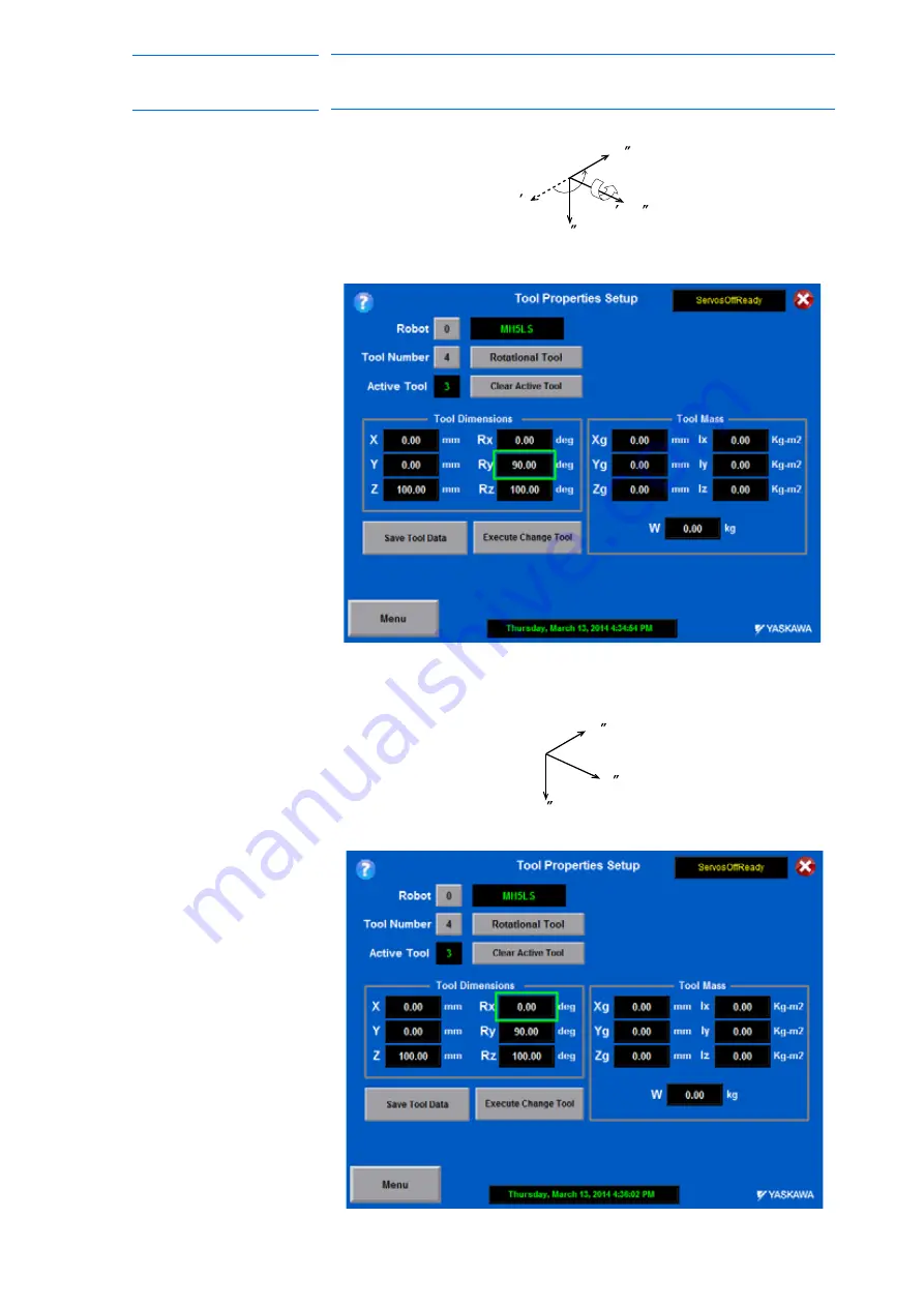
Ry must be the input rotation angle around Y’

flange coordinates.

– Rx must be the input rotation angle around X’

F

 of flange 

coordinates.

Z

F

Z

F

Y

F

(Y

)

F

X

F

Ry = 90

Z

F

Y

F

X

F

Rx = 0

64 of 121

Summary of Contents for Motoman MLX200

Page 1: ...8283 1CD Revision 8 MLX200 HARDWARE INSTALLATION SOFTWARE UPGRADE INSTRUCTIONS Upon receipt of the product and prior to initial operation read these instructions thoroughly and retain for future refer...

Page 2: ...ual is copyrighted property of Yaskawa and may not be sold or redistributed in any way You are welcome to copy this document to your computer or mobile device for easy access but you may not copy the...

Page 3: ...elds are replaced before operating this product The drawings and photos in this manual are representative examples and differences may exist between them and the delivered product YASKAWA may modify t...

Page 4: ...tomer is responsible for providing adequately trained personnel to operate program and maintain the equipment NEVER ALLOW UNTRAINED PERSONNEL TO OPERATE PROGRAM OR REPAIR THE EQUIPMENT We recommend ap...

Page 5: ...follow these important items WARNING Indicates a potentially hazardous situation which if not avoided could result in death or serious injury to personnel CAUTION Indicates a potentially hazardous si...

Page 6: ...nt whenever possible Always follow the predetermined operating procedure Ensure that you have a safe place to retreat in case of emergency Improper or unintended manipulator operation may result in in...

Page 7: ...e indications of R and TM are omitted CAUTION Perform the following inspection procedures prior to conducting manipulator teaching If problems are found repair them immediately and be sure that all ot...

Page 8: ...h the precautions on the warning labels WARNING The label described below is attached to the manipulator Observe the precautions on the warning labels Failure to observe this caution may result in inj...

Page 9: ...ety 1 7 1 6 2 Work Area Safety 1 9 1 6 3 Operation Safety 1 10 1 7 Notes for Moving and Transferring the MOTOMAN 1 11 1 8 Notes on MOTOMAN Disposal 1 12 2 Product Confirmation 2 1 2 1 Before Unpacking...

Page 10: ...Supply 5 1 5 2 Turning OFF the Power Supply 5 1 5 2 1 Turning OFF the Servo Power Emergency Stop 5 1 6 Test of Program Operation 6 1 6 1 Movement of the Axes 6 2 7 System Setup 7 1 7 1 Home Position C...

Page 11: ...x_x_x processor 10 6 10 9 Teach Pendant Software Upgrade 10 7 11 Teach Pendant Software Upgrade Procedure Fuji Pendant 11 1 11 1 Configure PC to use a Static IP 11 2 11 1 1 Prepare Pendant to Set the...

Page 12: ...283 1CD 168283 1CD Hardware Installation Software Upgrade Appendix A A 1 A 1 Rockwell MobileView Support A 1 A 1 1 Overview A 1 A 1 2 Components A 1 A 1 3 Wiring A 2 A 1 4 Software A 6 A 1 5 External...

Page 13: ...1 MLX200 Robot Control Module Components Several Hardware Installation Software Upgrade configurations are available and include the appropriate control panel servo amplifiers cables and components re...

Page 14: ...actoryTalk View Machine Edition or Studio Edition v6 1 Many of these items can be purchased from Yaskawa Contact your Yaskawa sales representative for more information 1 2 For Your Safety Robots gener...

Page 15: ...IONS based on concrete policies for safety management complying with related laws Observe the MANIPULATING INDUSTRIAL ROBOTS SAFETY ISO 10218 for safe operation of the robot Japan Only JIS B 8433 Rein...

Page 16: ...man MH5S II Instructions P N 172401 1CD Motoman MH5LS Instructions P N 161052 1CD Motoman MH5LS II Instructions P N 170780 1CD Motoman MH12 Instructions P N 167105 1CD Motoman HP20D Instructions P N 1...

Page 17: ...d Personnel in necessary areas in the factory Failure to observe these cautions may result in fire electric shock or injury due to contact with the manipulator and other equipment Strictly observe the...

Page 18: ...Hardware Installation Software Upgrade or other controllers and avoid inadvertently pushing buttons Failure to observe this caution may result in injury or damage by unexpected movement of the manipu...

Page 19: ...m with tool will not reach a side wall safeguarding or the drive panel Failure to observe this Warning may result in injury or damage resulting from unexpected movement of the manipulator Perform grou...

Page 20: ...may result in injury or damage to equipment If storing the manipulator temporarily before installation be sure to place it on a stable and flat surface and take precautions to prevent unauthorized per...

Page 21: ...with the manipulator while power is ON Post a warning sign stating Off limits During Operation at the entrance of the enclosure The gate of the safeguarding must be equipped with a safety interlock Be...

Page 22: ...of the manipulator Always view the manipulator from the front Always follow the predetermined operating procedure Always have an escape plan in mind in case the manipulator comes toward you unexpected...

Page 23: ...ent possibly causing injury or equipment damage MANDATORY Persons operating or inspecting the manipulator should be trained as required by applicable laws and company policies Refer to section 1 3 Spe...

Page 24: ...to observe this precaution could result in injury or damage resulting from fire power failure or operation error CAUTION When disposing of the MOTOMAN follow the applicable national local laws and re...

Page 25: ...ed in a crate along with any miscellaneous hardware and any accessories ordered 2 3 Contents Confirmation Confirm the contents of the delivery when the product arrives Standard delivery includes the f...

Page 26: ...80 VGA The features include a menu driven interface unique to the MLX200 Control Module environment by using the Teach Pendant the operator can teach and adjust the robots points perform programming e...

Page 27: ...y Stop Switch Implements an emergency stop condition and sends an emergency stop signal to the external equipment 3 Display 7 5 inch color LCD touch screen display 640 X 480 VGA 4 Power Lamp POWER A g...

Page 28: ...oftware Upgrade 2 Product Confirmation 2 4 Warranty ID Confirmation REGEN CABINET Example WARRANTY ID THE MANIPULATOR DRIVE PANEL AMPLIFIERS CONTROLLER MODULE AND REGEN CABINET SHOULD HAVE THE SAME WA...

Page 29: ...ssue along with complete contact information Please allow approximately 24 to 36 hours for a response to your inquiry Please have the following information ready before you call techsupport motoman co...

Page 30: ...55 C 23 to 131 F during operation transportation and maintenance Humidity must be low with no condensation 10 85 RH It must be a place with little dirt dust or water No flammable or corrosive liquids...

Page 31: ...Install the drive panel in a location from which you can easily inspect it 4 Install the drive panel at least 500 mm from the nearest wall to allow maintenance access 5 See Fig 3 1 Location of MLX200...

Page 32: ...ING HOLES MINIMUM CLEARANCE ABOVE EQIPMENT PANEL C AIR FLOW Table 3 1 MLX200 Drive Panel Dimensions mm Manipulator Drive Panel Approximate Weight kg A B C D D1 E E1 MH5S MH5LS MH5S II MH5LS II 159181...

Page 33: ...6 0 14 5 29 0 4X R4 MAX Cutout For Pigtail Power 28C Manipulator Cable 96 0 44 0 22 0 48 0 54 0 27 0 4X M4 Clearance or Tap 4X R9 MAX Cutout For Pigtail Regen Resistors 4X 4 0 33 0 29 4 29 4 14 7 14 7...

Page 34: ...en Resistors 4X 4 0 33 0 29 4 29 4 14 7 14 7 Cutout For Optional Fuj Teach Pendant Cable 24 1 0 1 0 0 22 9 0 1 0 0 45 Cutout For Pigtail Encoder 1BC Manipulator Cable 2X M4 Clearance or Tap 34 5 69 0...

Page 35: ...anipulator Cable 2X M4 Clearance or Tap 34 5 69 0 28 0 56 0 14 5 29 0 4X R4 MAX 93 0 46 5 14 0 28 0 40 5 81 0 Cutout For Pigtail Power 2BC Manipulator Cable 4X R4 MAX 2X M4 Clearance or Tap Cutout For...

Page 36: ...tion 7 The Regen cabinet may produce significant heat and should be mounted outside the main cabinet with the fans directed up See Fig 3 5 a and Fig 3 5 b Fig 3 5 a MH5S MH5S II MH5LS MH5LS II Regen C...

Page 37: ...8283 1CD 168283 1CD Hardware Installation Software Upgrade Fig 3 5 b MH12 HP20D MPK50 MPL80 MPL160 MPL300 MPL80 II MPL160 II MPL300 II Regen Cabinet Mounting Dimensions and Weight 415 387 95 175 175 5...

Page 38: ...panel is supplied with one Emergency Stop button and one Auto Manual button that should be mounted to the enclosure for users to interact with These buttons are wired using a cable with approximately...

Page 39: ...ower cannot be turned ON unless the door is closed Interlocks prevent power from being turned ON Failure to observe this caution may result in fire and electric shock Any occurrence during wiring whil...

Page 40: ...le use metal ducts or conduit to isolate electrical signal interference If cables must be crossed run the power cables perpendicular across the signal cables Confirm the connector and cable numbers to...

Page 41: ...power turns OFF Connect the power supply to a stable power source that is not prone to power fluctuations NOTE It is the customer s responsibility to provide adequate breaker fusing for their applicat...

Page 42: ...capacity in consideration of the MLX200 panel power capacity for the manipulator to be used The maximum load value payload operation speed and frequency etc is displayed However the power capacity is...

Page 43: ...ck Customer must provide fusing Perform grounding in accordance with all relevant local and national electrical codes The size of ground wire must the same as listed on Table 4 1 MLX200 Power Capacity...

Page 44: ...m the shape and size of the cable connector the key fitting and the position of the pins of the manipulator Push the cable connector into the manipulator side connector firmly and tighten securely NOT...

Page 45: ...between the Master and slave Drive Panel When using a dual robot the basic connections for the slave robot is the same as the first except No MLX200 Control Module Make the interlock cable connection...

Page 46: ...perated when an emergency stop button is pressed Press the emergency stop button and the servo power supply is turned off The brake operates once the servo power supply is turned OFF and the manipulat...

Page 47: ...to retreat to in case of emergency Improper or unintentional manipulator operation can result in injury Prior to performing the following operations be sure that there is no one within the P point max...

Page 48: ...the appropriate axis buttons on the MLX HMI The following figures illustrate each axis of motion in the joint coordinates Fig 6 1 4 Axis Manipulator NOTE Be sure to remove all items from the area bef...

Page 49: ...re Upgrade Fig 6 2 5 Axis Manipulator Fig 6 3 6 Axis Manipulator A4 A3 A4 A3 A2 A2 A1 A1 A0 A0 Wrist Wrist flange Lower arm L arm Upper arm U arm Rotary head S head Manipulator base Wrist Upper arm U...

Page 50: ...n Software Upgrade 6 Test of Program Operation 6 1 Movement of the Axes Fig 6 4 7 Axis Manipulator Z X Y A2 A2 A5 A5 A3 A3 A1 A1 A4 A4 A0 A0 A6 A6 Reference coordinates of base robot axes T axis B axi...

Page 51: ...may result if the manipulator cannot be stopped in case of an emergency Observe the following precautions when performing teaching operations within the P point maximum envelope of the manipulator Vi...

Page 52: ...an take its posture for the home position There are two operations for home position calibration Axes can be moved individually Recalibrate the home position for the individual axes that were affected...

Page 53: ...Password expert The main screen shows EXPERT when successful 2 Press the Menu button and then select the Teach Screen button The MLX200 Teaching and Jogging screen appears 3 Set Jog Speed to Inch and...

Page 54: ...Establish the Home position Press Get Current The values update Alternative the home position values can also be read from a home position sticker located on the robot and entered into the Home Offse...

Page 55: ...erified because of the change of home position Do this from the main screen using the green button available NOTE When communication is re established the Axis Position list values should be close to...

Page 56: ...ition of the Robot In case of MH5S the home position are as follows NOTE Other manipulator models have different positions Always refer to MANIPULATOR INSTRUCTIONS for the correct manipulator model Wr...

Page 57: ...ncoder system The manipulator was moved after the power supply was turned OFF If there is an error with the encoder system the manipulator may stall when playback is started If the absolute data allow...

Page 58: ...Number of Tools There are 24 tool files numbered 0 to 23 7 2 1 2 Registering Coordinate Data When the number input operation is used for registering the tool file input the TCP of the tool on the flan...

Page 59: ...message Switch to TEACH mode to set appears if the system is left in Play mode Fig 7 1 Setup Tool Properties 3 While in Teach Mode press the tool number to select the Tool Number and modify Press the...

Page 60: ...7 10 168283 1CD 168283 1CD Hardware Installation Software Upgrade 7 System Setup 7 2 Tool Data Setting Fig 7 2 Tool A ZF TCP Tool A 260 mm 60 of 121...

Page 61: ...o store the modified tool information NOTE Tool data is not saved to the MLX200 Control Module until the Save Tool Data button is clicked If data is incorrectly modified simply close this screen and n...

Page 62: ...ing 7 Click on the Execute Change Tool button to have the robot use this tool when moving in the Tool Coordinate system The tool appears as the active tool on the Teach screen Fig 7 4 Active Tool Fram...

Page 63: ...flange coordinates and the tool coordinates The angle when the flange coordinates are rotated to meet to the tool coordinates becomes an input value Clockwise toward the arrow is the positive directi...

Page 64: ...ion Software Upgrade 7 System Setup 7 2 Tool Data Setting Ry must be the input rotation angle around Y F flange coordinates Rx must be the input rotation angle around X F of flange coordinates Z F Z F...

Page 65: ...such as torches tools and guns must be registered and the position of the TCP must be defined Tool calibration is a function that enables this dimensional information to be registered easily and accu...

Page 66: ...correctly registered by performing a TCP fixed operation like the one shown below in any coordinate system other than the joint 1 Move the R B or T axes using the axis key By pressing the axis keys fo...

Page 67: ...w the manipulator from the front whenever possible Always follow the predetermined operating procedure Always have an escape plan in mind in case the manipulator comes toward you unexpectedly Ensure t...

Page 68: ...peration 5 C to 55 C During transit and storage Relative Humidity 10 to 85 RH non condensing Power Supply 24 VDC Allen Bradley Grounding Grounding resistance 100 or less Exclusive grounding Digital I...

Page 69: ...ow a similar layout Small Capacity Fig 8 1 Configuration MPL80 Shown MLX200 Control Module Not used on slave Servo Amplifiers Table 8 2 a MLX200 Parts Description MH5S MH5LS MH5S II MH5LS II MLX200 Ro...

Page 70: ...Length 5M 156874 2 N A 156874 2 N A Regen Resistor Unit 159036 2 159036 2 159036 2 159036 2 Cable Regen Resistor Unit 1M 159081 1 159081 1 159081 1 159081 1 MLX200 Control Module 167522 1 167522 1 16...

Page 71: ...nipulator View the manipulator from the front whenever possible Always follow the predetermined operating procedure Always have an escape plan in mind in case the manipulator comes toward you unexpect...

Page 72: ...CAUTION Do not connect two signals to the same contact point Prepare two individual contact points Since the power supply for each signal is unique it will cause a fault in the safety relay CR502 if...

Page 73: ...ON Always connect the signals after removing the jumpers If the jumpers are not removed injury or damage to machinery may result and the external emergency stop will not work even if the signal is inp...

Page 74: ...disabled in teach mode Example devices include Light Curtains and Safety Gates Fig 9 2 Connection for Safety Plug CAUTION Always connect the signals after removing the jumpers If the jumpers are not...

Page 75: ...r is open The safety plug input signal is connected to the interlock signal from the gate If the servo power is ON when the interlock signal is input the servo power turns OFF The servo power cannot b...

Page 76: ...ency stop do not work even if the signal is input NOTE If multiple External Enable Switches are present in the system all contacts must be wired in series to the TB2 5 status input If a teach pendant...

Page 77: ...e signal is input the servo power cannot be turned ON E Stop Status TB2 4 Single Emergency Stop Status Monitor Wired to include switch with or without Teach Pendant Allows the software to know the sta...

Page 78: ...n the SERVO ON state MANUAL 1 MANUAL 1 MANUAL 2 MANUAL 2 TB2 18 TB2 19 TB2 20 TB2 19 Applicable Manual Teach Mode Selection Switch included and wired Used to indicate mode selection When these signals...

Page 79: ...H5LS II MH12 HP20D MPK50 MPL80 MPL80 II MPL160 MPL160 II MPL300 MPL300 II Model Model Model Model Model Model SV0 157430 5 SV0 157430 1 SV0 157430 6 SV0 157430 9 SV0 157430 9 SV0 157430 9 SV1 157430 5...

Page 80: ...ifics and system operations data is imported 10 1 Upgrade the Application on the MLX200 Control Module The MLX200 Control Module software upgrades includes a maintenance tool to make it easier to upgr...

Page 81: ...Module 6 From the Maintenance Operations screen on the control module click on the Upload Restore category on the left and select the Update MLX200 Control Module Firmware Press the Execute button 7...

Page 82: ...pgrade the Application on the MLX200 Control Module 9 To reboot the MLX200 Control Module click on the Settings category on the left and select the Update MLX200 Control Module Firmware Press the Exec...

Page 83: ...es a With the PC connected to the Ethernet switch double click on the MLxData200 exe file 2 On the MLxData200 screen select the robot number the PLC processor slot number and the IP address of the PLC...

Page 84: ...ogix Ladder 1 Insert devices into the I O Configuration of the ladder and copy board software revision numbers from the old ladder 10 6 Import Tasks into the New RSLogix Ladder 1 In the RSLogix Contro...

Page 85: ...l data in section 10 2 Export Robot Data for RSLogix Ladder is imported into the new RSLogix ladder 4 Press Start Import of Listed Files 5 After files are imported a confirmation message will be displ...

Page 86: ...Teach Pendant Software Upgrade 10 9 Teach Pendant Software Upgrade If a Fuji teach pendant is installed on the cell complete chapter 11 Teach Pendant Software Upgrade Procedure Fuji Pendant steps If...

Page 87: ...MobileView is used this section is not applicable Follow the steps below when installing a new MLX software version or adjusting the IP address of the PLC or teach pendant in the system By following t...

Page 88: ...cedure Fuji Pendant 11 1 Configure PC to use a Static IP 11 1 Configure PC to use a Static IP 1 Attach Ethernet cable between the teach pendant and the PC 2 Open the Internet Protocol TCP IP Propertie...

Page 89: ...to section 11 1 3 Setting IP Address for Pendant 11 1 2 Prepare Pendant to Change IP Address for an Upgraded System Ensure the screen in section 11 1 1 Prepare Pendant to Set the IP Address for the NE...

Page 90: ...ess Setting Finished on the touch screen bottom right 5 Verify the IP address displays on the Main Setting screen 6 Verify Communication between the computer and the teach pendant a Start a command pr...

Page 91: ...vigate to Device Connection Settings and then double click on PLC1 In the window on the right change the tabbed view to show Target Settings as shown 4 Enter the IP address as 192 168 1 2 NOTE The IP...

Page 92: ...e Fuji V SFTV5 Monitouch Program 5 Adjust the network table by navigating to Ethernet and double clicking on Network Table in the left hand window 6 Set the PLC IP to 192 168 1 2 refer to step 3 for a...

Page 93: ...ndant Version 5 1 Select Transfer from the File menu and verify the IP address of the pendant at bottom of the screen is correct 192 168 1 100 2 Press the first PC button to transfer from the PC to th...

Page 94: ...C and a blue message in the bottom left corner of the Teach Pendant saying TransferData indicating a transfer is taking place 5 Observe when transfer is complete nothing appears to confirm success NOT...

Page 95: ...168283 1CD Hardware Installation Software Upgrade 11 4 Setup the Fuji V SFTV6 Monitouch Program 1 Start the Fuji V SFTV6 Monitouch programming software 2 Open the project file v8 3 From Main Menu go t...

Page 96: ...arm PLC test station that cycles across the EtherNet IP Module into No 0 of the PLC Table that appears 7 Close both windows and save the project CAUTION Do not edit the PLC Table Port Name Editing the...

Page 97: ...n 2 Observe the IP address displayed at the bottom of this window a If the correct address is not displayed press Communication Settings button and select Ethernet Enter the IP address 192 168 1 100 a...

Page 98: ...ttom left corner of the Teach Pendant indicating Transferring Data when project files are transferring to the hardware If a failure notice appears If the message Receive Waiting Time Exceeded is recei...

Page 99: ...1 6 Install the MLX Version Label 11 13 168283 1CD 168283 1CD Hardware Installation Software Upgrade 11 6 Install the MLX Version Label Place the MLX version label on the back of the pendant to indica...

Page 100: ...ort labeled CN7 2 Start the SigmaWin program select Online mode and then click Search 3 When the Search Condition Setting screen appears select Only Sigma V under the Target Servopack Series Setting s...

Page 101: ...on Software Upgrade 5 Observe the Searching screen appears indicating that SigmaWin has begun searching 6 Observe a Servopack and Servomotor with Option is available if successful Click on the item in...

Page 102: ...tallation Software Upgrade 12 Sigma 5 Amplifier Parameter Upgrade Procedure 8 Select Import from the Parameter Editing screen 9 Select the file for this servopack and press Open 10 Select the checkbox...

Page 103: ...are transferring 12 Press OK when the Verification screen appears 13 Move the USB cable to the next servo pack Select the File tab and press Connect 14 Repeat step 2 through step 12 for all servo pac...

Page 104: ...solutions 13 2 Configuring Factory Talk Administration Console 1 Factory Talk ME station requires a few configuration steps to display the MLX HMI correctly Before you can run the HMI runtime file you...

Page 105: ...p 10 Fig 13 3 FT Administration Console Explorer with PLCs 5 To allow for the Factory Talk Administration Console to see the PLC you will need to add a driver Right click on the RSLinx Enterprise in t...

Page 106: ...properties screen shown in Fig 13 6 Administration Console Driver Configuration Fig 13 6 Administration Console Driver Configuration 8 If the computer is connected to the PLC then you will start to se...

Page 107: ...can name the device and assign it an IP address see Fig 13 8 Fig 13 8 Administration Console Device Properties 10 Once you have entered the correct IP address click OK After this step you should see...

Page 108: ...iguring Factory Talk Administration Console 13 If the processor names are not the same highlight the PLC processor in the FactoryTalk Administration Console Right Click and select Properties Change th...

Page 109: ...n 3 b If the HMI Customization option was not purchased select the New Tab enter any Application Name MLX200_test and press Create 4 Under the Explorer window in the Application tab find RSLinx Enterp...

Page 110: ...I Communications Setup Procedure 13 3 Copy PLC Design to Runtime 10 Highlight the Control Module and press Copy from Design to Runtime When prompted press Yes 11 Press OK at the bottom of the screen a...

Page 111: ...p the HMI 13 8 168283 1CD 168283 1CD Hardware Installation Software Upgrade 13 4 Starting up the HMI 1 Click on the MLX200_HMI mer file to start up FactoryTalk View Machine Edition 2 Select YES at the...

Page 112: ...D Hardware Installation Software Upgrade 13 HMI Communications Setup Procedure 13 4 Starting up the HMI 4 Select Networks and Communications and press Enter 5 Select RSLinx Enterprise Communications a...

Page 113: ...D 168283 1CD Hardware Installation Software Upgrade 6 Highlight the MLX200 processor and press Close three times to get back to the main screen 7 Click on Application Settings see FactoryTalk View ME...

Page 114: ...PLC processor and press OK and then Close two times to get back to the main screen 11 Press Run Application the software shows display without shadows when all steps have been completed correctly 12...

Page 115: ...we did sell this product and instead would simply be passing along a product with additional mark up Our path forward is to suggest components and show the wiring example in this manual Customers who...

Page 116: ...common industrial knowledge should always be applied when working around electricity The following diagrams are for reference only Fig A 1 a Pendant Interface without Pendant Includes Junction Box and...

Page 117: ...G IS 18 AWG WHT BLU UNLESS OTHERWISE SPECIFIED REMOVE EXISTING 18 AWG ORANGE JUMPERS TB2 10 TO TB2 13 AND TB2 17 TO TB2 20 REMOVE EXSITING 18 AWG ORANGE JUMPERS TB2 8 TO TB2 9 AND TB2 15 TO TB2 16 1 1...

Page 118: ...9 538 537 536 534 535 533 532 531 530 529 528 527 526 525 521 524 523 522 314 S22 S21 S12 S11 A1 S34 A2 S52 CR534 313A MSR 127TP X1 3 X1 4 X1 6 X1 5 536 TEACH PENDANT E STOP 502 505 606 BLU BLU BLU BL...

Page 119: ...PNK RED RED SO2 SAFETY RESET SAFETY RELAY RESET 504 CN1 23 CN1 24 610 PNK RED RED RED 611 PNK BLK BLK BLK CN1 6 604 GRN BLK 24VIN TB2 1 A1 A2 CR611 TB2 6 CN1 12 608 BLU BLK BLK 0SV HWBB STATUS MONITOR...

Page 120: ...appropriate user login is used MLX200_HMI_ForPCorPanelView APA Software should be installed in any remote stations like PanelView HMI displays This display software will not allow access to Teaching o...

Page 121: ...86 10 6788 2878 YASKAWA SHOUGANG ROBOT Co Ltd 426 Udyog Vihar Phase IV Gurgaon Haryana India Fax 91 124 475 8542 Phone 91 124 475 8500 YASKAWA India Private Ltd Robotics Division YASKAWA Electric Chi...

Reviews: