1-4
FEATURES
INSTRUMENT FUNCTIONS
EAUB1392
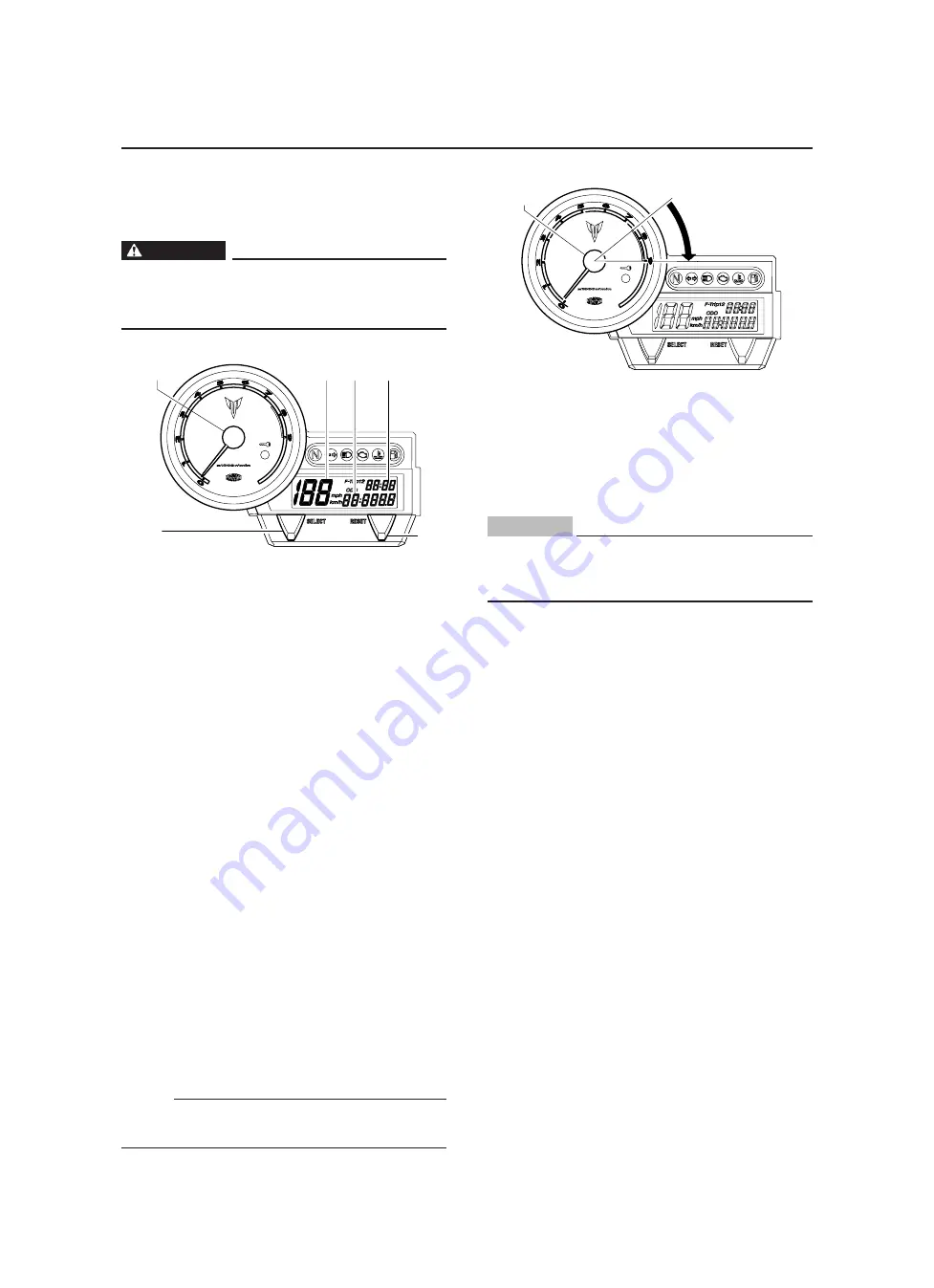
Multi-function meter unit
EWA12421
WARNING
Be sure to stop the vehicle before making
any setting changes to the multi-function
meter unit.
1. Speedometer
2. Tachometer
3. Clock
4. Odometer/Tripmeters/Fuel reserve tripmeter
5. “SELECT” button
6. “RESET” button
The multi-function meter unit is equipped with
the following:
• a speedometer (which shows the riding
speed)
• a tachometer (which shows engine speed)
• an odometer (which shows the total distance
traveled)
• two tripmeters (which show the distance
traveled since they were last set to zero)
• a fuel reserve tripmeter (which shows the
distance traveled since the fuel level warning
light came on)
• a clock
• a self-diagnosis device
• an indicator lights brightness control mode.
To switch the speedometer and odometer/trip-
meter displays between kilometers and miles,
push the “SELECT” and “RESET” buttons to-
gether and turn the key to “ON”. When the dig-
its start flashing on the display, push the “SE-
LECT” button to choose kilometers or miles.
NOTE:
Be sure to turn the key to “ON” before using the
“SELECT” and “RESET” buttons.
1
4
3
5
2
6
Tachometer
1. Tachometer
2. Red zone
The electric tachometer allows the rider to mon-
itor the engine speed and keep it within the ide-
al power range.
ECA10031
CAUTION:
Do not operate the engine in the tachome-
ter red zone. Red zone: 7500 r/min and
above.
1
2
Summary of Contents for MT-03
Page 7: ......
Page 9: ......
Page 25: ......
Page 53: ...2 28 COOLING SYSTEM DIAGRAMS 1 2 3 4 5 6 7 8 9 5 10 11 A B C ...
Page 56: ...2 31 LUBRICATION CHART Pressure feed Splashed scavenge ...
Page 57: ...2 32 LUBRICATION DIAGRAMS LUBRICATION DIAGRAMS A A 1 3 2 2 4 A A A A ...
Page 59: ...2 34 LUBRICATION DIAGRAMS A A A A 3 1 2 3 4 ...
Page 60: ...2 35 LUBRICATION DIAGRAMS 1 Oil delivery pipe 2 2 Oil delivery pipe 1 3 Oil filter 4 Oil pump ...
Page 61: ...2 36 LUBRICATION DIAGRAMS 1 7 2 3 4 5 6 A ...
Page 63: ...2 38 LUBRICATION DIAGRAMS 1 6 5 4 3 2 ...
Page 65: ...2 40 CABLE ROUTING CABLE ROUTING ...
Page 67: ...2 42 CABLE ROUTING ...
Page 69: ...2 44 CABLE ROUTING ...
Page 71: ...2 46 CABLE ROUTING ...
Page 73: ...2 48 CABLE ROUTING ...
Page 75: ...2 50 CABLE ROUTING ...
Page 77: ...2 52 CABLE ROUTING ...
Page 79: ...2 54 CABLE ROUTING ...
Page 81: ...2 56 CABLE ROUTING ...
Page 83: ...2 58 CABLE ROUTING ...
Page 85: ...2 60 CABLE ROUTING ...
Page 87: ......
Page 121: ......
Page 177: ...4 54 FRONT FORK WARNING Make sure the brake hoses are routed prop erly ...
Page 271: ......
Page 273: ......
Page 287: ......
Page 325: ......
Page 339: ...8 12 CHARGING SYSTEM 2 A C magneto 5 Rectifier regulator 7 Battery 8 Main fuse ...
Page 341: ...8 14 CHARGING SYSTEM ...
Page 355: ...8 28 COOLING SYSTEM ...
Page 365: ...8 38 IMMOBILIZER SYSTEM ...
Page 366: ...8 39 ELECTRICAL COMPONENTS EAS27970 ELECTRICAL COMPONENTS ...
Page 368: ...8 41 ELECTRICAL COMPONENTS ...
Page 370: ...8 43 ELECTRICAL COMPONENTS EAS27980 CHECKING THE SWITCHES ...
Page 389: ......
Page 391: ......
Page 397: ...COLOR CODE ...
Page 398: ......
Page 399: ...YAMAHA MOTOR ITALIA S P A ...
Page 400: ...MT 03 2006 WIRING DIAGRAM ...


