1-5
FEATURES
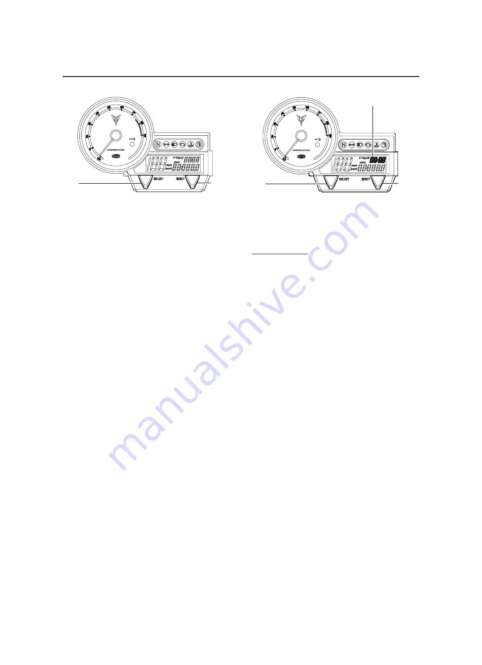
Odometer, tripmeter modes
1. “SELECT” button
2. “RESET” button
Pushing the “SELECT” button switches the dis-
play between the odometer mode “ODO” and
the tripmeter modes “TRIP 1” and “TRIP 2” in
the following order:
ODO
6
TRIP 1
6
TRIP 2
6
ODO
If the fuel level warning light comes on, the
odometer display will automatically change to
the fuel reserve tripmeter mode “F-TRIP” and
start counting the distance traveled from that
point. In that case, push the “SELECT” button
to switch the display between the various trip-
meter, odometer modes in the following order:
F-TRIP
6
ODO
6
TRIP 1
6
TRIP 2
6
F-TRIP
To reset a tripmeter, select it by pushing the “SE-
LECT” button, and then push the “RESET” button
for at least four seconds. If you do not reset the
fuel reserve tripmeter manually, it will reset itself
automatically and the display will return to the pri-
or mode after refueling and traveling 5 km (3 mi).
1
2
Clock mode
1. Clock
2. “SELECT”
button
3. “RESET”
button
Turn the key to “ON”.
To set the clock
1. Push the “SELECT” button for at least two
seconds.
2. When the hour digits start flashing, push the
“RESET” button to set the hours.
3. Push the “SELECT” button, and the minute
digits will start flashing.
4. Push the “RESET” button to set the minutes.
5. Push the “SELECT” button, and then re-
lease it to start the clock.
1
2
3
Summary of Contents for MT-03
Page 7: ......
Page 9: ......
Page 25: ......
Page 53: ...2 28 COOLING SYSTEM DIAGRAMS 1 2 3 4 5 6 7 8 9 5 10 11 A B C ...
Page 56: ...2 31 LUBRICATION CHART Pressure feed Splashed scavenge ...
Page 57: ...2 32 LUBRICATION DIAGRAMS LUBRICATION DIAGRAMS A A 1 3 2 2 4 A A A A ...
Page 59: ...2 34 LUBRICATION DIAGRAMS A A A A 3 1 2 3 4 ...
Page 60: ...2 35 LUBRICATION DIAGRAMS 1 Oil delivery pipe 2 2 Oil delivery pipe 1 3 Oil filter 4 Oil pump ...
Page 61: ...2 36 LUBRICATION DIAGRAMS 1 7 2 3 4 5 6 A ...
Page 63: ...2 38 LUBRICATION DIAGRAMS 1 6 5 4 3 2 ...
Page 65: ...2 40 CABLE ROUTING CABLE ROUTING ...
Page 67: ...2 42 CABLE ROUTING ...
Page 69: ...2 44 CABLE ROUTING ...
Page 71: ...2 46 CABLE ROUTING ...
Page 73: ...2 48 CABLE ROUTING ...
Page 75: ...2 50 CABLE ROUTING ...
Page 77: ...2 52 CABLE ROUTING ...
Page 79: ...2 54 CABLE ROUTING ...
Page 81: ...2 56 CABLE ROUTING ...
Page 83: ...2 58 CABLE ROUTING ...
Page 85: ...2 60 CABLE ROUTING ...
Page 87: ......
Page 121: ......
Page 177: ...4 54 FRONT FORK WARNING Make sure the brake hoses are routed prop erly ...
Page 271: ......
Page 273: ......
Page 287: ......
Page 325: ......
Page 339: ...8 12 CHARGING SYSTEM 2 A C magneto 5 Rectifier regulator 7 Battery 8 Main fuse ...
Page 341: ...8 14 CHARGING SYSTEM ...
Page 355: ...8 28 COOLING SYSTEM ...
Page 365: ...8 38 IMMOBILIZER SYSTEM ...
Page 366: ...8 39 ELECTRICAL COMPONENTS EAS27970 ELECTRICAL COMPONENTS ...
Page 368: ...8 41 ELECTRICAL COMPONENTS ...
Page 370: ...8 43 ELECTRICAL COMPONENTS EAS27980 CHECKING THE SWITCHES ...
Page 389: ......
Page 391: ......
Page 397: ...COLOR CODE ...
Page 398: ......
Page 399: ...YAMAHA MOTOR ITALIA S P A ...
Page 400: ...MT 03 2006 WIRING DIAGRAM ...


