


3-10
ENGINE
5. Install the engine oil tank dipstick.
6. Start the engine, warm it up for several min-
utes, and then turn it off.
7. Check the engine oil level again.
NOTE:
Before checking the engine oil level, wait a few
minutes until the oil has settled.
EAS00076
CHANGING THE ENGINE OIL
1. Start the engine, warm it up for several min-
utes, and then turn it off.
2. Place the motorcycle on its side stand, then
place an oil pan under the oil tank and anoth-
er under the engine to collect the used oil.
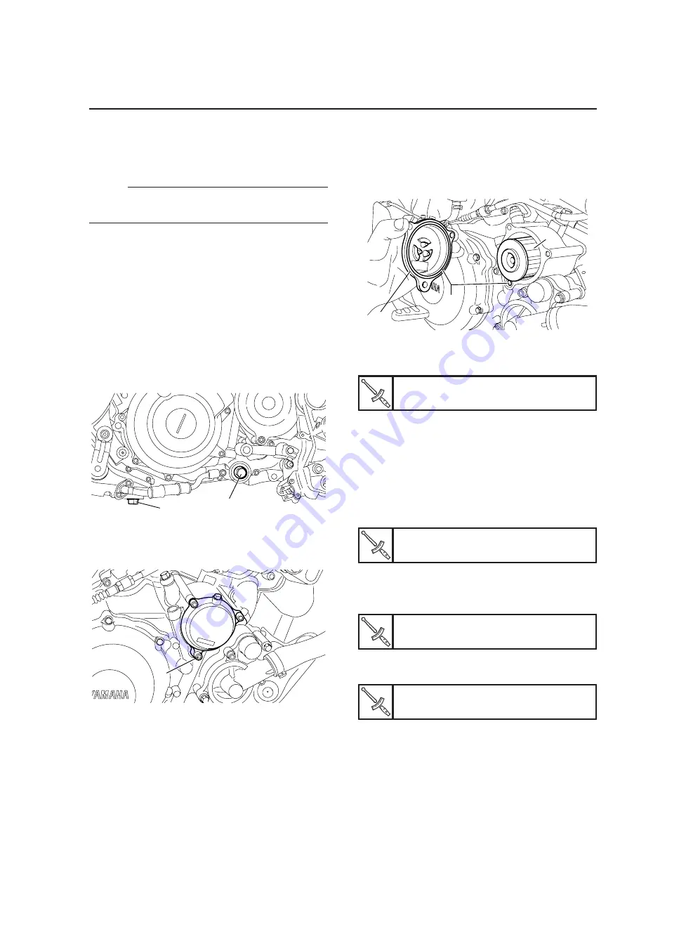
3. Remove:
• Engine oil tank dipstick
• Engine oil crankcase drain bolt “1”
• Engine oil tank drain bolt “2”
4. Remove:
• Oil filter element drain bolt “1”
5. Drain:
• Engine oil (completely from the crankcase
and the oil tank)
6. If the oil filter element is also to be replaced,
perform the following procedure.
1
2
1
▼▼▼▼▼▼▼▼▼▼▼▼▼▼▼▼▼▼▼▼▼▼▼▼▼▼▼▼▼▼▼▼
a. Remove the oil filter element cover “1” and
oil filter element “2”.
b. Check the O-rings “3” and replace them if
they are cracked or damaged.
c. Install the new oil filter element and the oil fil-
ter element cover.
2
3
1
7. Check:
• Engine oil drain bolt gasket
Damage
→
Replace.
8. Install:
• Engine oil drain bolt (crankcase) (along with
the gasket)
• Engine oil drain bolt (oil tank) (along with the
gasket)
• Oil filter element drain bolt
9. Fill:
• Oil tank (with the specified amount of the
recommended engine oil)
Oil filter element cover bolt
10 Nm (1.0 m·kg, 7.2 ft·lb)
▼▼▼▼▼▼▼▼▼▼▼▼▼▼▼▼▼▼▼▼▼▼▼▼▼▼▼▼▼▼▼▼
Engine oil drain bolt (crankcase)
30 Nm (3.0 m·kg, 22 ft·lb)
Engine oil drain bolt (oil tank)
30 Nm (3.0 m·kg, 22 ft·lb)
Oil filter element drain bolt
10 Nm (1.0 m·kg, 7.2 ft·lb)
Summary of Contents for MT-03
Page 7: ......
Page 9: ......
Page 25: ......
Page 53: ...2 28 COOLING SYSTEM DIAGRAMS 1 2 3 4 5 6 7 8 9 5 10 11 A B C ...
Page 56: ...2 31 LUBRICATION CHART Pressure feed Splashed scavenge ...
Page 57: ...2 32 LUBRICATION DIAGRAMS LUBRICATION DIAGRAMS A A 1 3 2 2 4 A A A A ...
Page 59: ...2 34 LUBRICATION DIAGRAMS A A A A 3 1 2 3 4 ...
Page 60: ...2 35 LUBRICATION DIAGRAMS 1 Oil delivery pipe 2 2 Oil delivery pipe 1 3 Oil filter 4 Oil pump ...
Page 61: ...2 36 LUBRICATION DIAGRAMS 1 7 2 3 4 5 6 A ...
Page 63: ...2 38 LUBRICATION DIAGRAMS 1 6 5 4 3 2 ...
Page 65: ...2 40 CABLE ROUTING CABLE ROUTING ...
Page 67: ...2 42 CABLE ROUTING ...
Page 69: ...2 44 CABLE ROUTING ...
Page 71: ...2 46 CABLE ROUTING ...
Page 73: ...2 48 CABLE ROUTING ...
Page 75: ...2 50 CABLE ROUTING ...
Page 77: ...2 52 CABLE ROUTING ...
Page 79: ...2 54 CABLE ROUTING ...
Page 81: ...2 56 CABLE ROUTING ...
Page 83: ...2 58 CABLE ROUTING ...
Page 85: ...2 60 CABLE ROUTING ...
Page 87: ......
Page 121: ......
Page 177: ...4 54 FRONT FORK WARNING Make sure the brake hoses are routed prop erly ...
Page 271: ......
Page 273: ......
Page 287: ......
Page 325: ......
Page 339: ...8 12 CHARGING SYSTEM 2 A C magneto 5 Rectifier regulator 7 Battery 8 Main fuse ...
Page 341: ...8 14 CHARGING SYSTEM ...
Page 355: ...8 28 COOLING SYSTEM ...
Page 365: ...8 38 IMMOBILIZER SYSTEM ...
Page 366: ...8 39 ELECTRICAL COMPONENTS EAS27970 ELECTRICAL COMPONENTS ...
Page 368: ...8 41 ELECTRICAL COMPONENTS ...
Page 370: ...8 43 ELECTRICAL COMPONENTS EAS27980 CHECKING THE SWITCHES ...
Page 389: ......
Page 391: ......
Page 397: ...COLOR CODE ...
Page 398: ......
Page 399: ...YAMAHA MOTOR ITALIA S P A ...
Page 400: ...MT 03 2006 WIRING DIAGRAM ...