


8-50
ELECTRICAL COMPONENTS
3. Remove:
• Battery band
• Battery
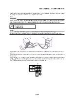
4. Check:
• Battery charge
▼▼▼▼▼▼▼▼▼▼▼▼▼▼▼▼▼▼▼▼▼▼▼▼▼▼▼▼▼▼▼▼
a. Connect a pocket tester to the battery termi-
nals.
• Positive tester probe
→
positive battery terminal
• Negative tester probe
→
negative battery terminal
NOTE:
• The charge state of an MF battery can be
checked by measuring its open-circuit voltage
(i.e., the voltage when the positive battery ter-
minal is disconnected).
• No charging is necessary when the open-cir-
cuit voltage equals or exceeds 12.8 V.
b. Check the charge of the battery, as shown in
the charts and the following example.
Example
Open-circuit voltage = 12.0 V
Charging time = 6.5 hours
Charge of the battery = 20–30%
▼▼▼▼▼▼▼▼▼▼▼▼▼▼▼▼▼▼▼▼▼▼▼▼▼▼▼▼▼▼▼▼
5. Charge:
• Battery
(refer to the appropriate charging method)
EWA13300
WARNING
Do not quick charge a battery.
EWA13300
CAUTION:
•
Never remove the MF battery sealing caps.
•
Do not use a high-rate battery charger since
it forces a high-amperage current into the
battery quickly and can cause bat-tery over-
heating and battery plate damage.
•
If it is impossible to regulate the charging
current on the battery charger, be careful
not to overcharge the battery.
•
When charging a battery, be sure to re-
move it from the vehicle. (If charging has
to be done with the battery mounted on
the vehicle, disconnect the negative bat-
tery lead from the battery terminal.)
•
To reduce the chance of sparks, do not
plug in the battery charger until the battery
charger leads are connected to the bat-
tery.
•
Before removing the battery charger lead
clips from the battery terminals, be sure to
turn off the battery charger.
•
Make sure the battery charger lead clips
are in full contact with the battery terminal
and that they are not shorted. A corroded
battery charger lead clip may generate
heat in the contact area and a weak clip
spring may cause sparks.
•
If the battery becomes hot to the touch at
any time during the charging process, dis-
connect the battery charger and let the bat
tery cool before reconnecting it. Hot bat-
teries can explode!
•
As shown in the following illustration, the
open-circuit voltage of an MF battery sta-
bilizes about 30 minutes after charging
has been completed. Therefore, wait 30
minutes after charging is completed be-
fore measuring the open-circuit voltage.
▼▼▼▼▼▼▼▼▼▼▼▼▼▼▼▼▼▼▼▼▼▼▼▼▼▼▼▼▼▼▼▼
Charging method using a variable-current
(voltage) charger
a. Measure the open-circuit voltage prior to
charging.
NOTE:
Voltage should be measured 30 minutes after
the engine is stopped.
b. Connect a charger and ammeter to the bat-
tery and start charging.
NOTE:
Set the charging voltage at 16–17 V.If the set-
ting is lower, charging will be insufficient. If too
high, the battery will be over-charged.
c. Make sure that the current is higher than the
standard charging current written on the bat-
tery.
NOTE:
If the current is lower than the standard charg-
ing current written on the battery, set the charg-
ing voltage adjust dial at 20–24 V and monitor
the amperage for 3–5 minutes to check the bat-
tery.
Summary of Contents for MT-03
Page 7: ......
Page 9: ......
Page 25: ......
Page 53: ...2 28 COOLING SYSTEM DIAGRAMS 1 2 3 4 5 6 7 8 9 5 10 11 A B C ...
Page 56: ...2 31 LUBRICATION CHART Pressure feed Splashed scavenge ...
Page 57: ...2 32 LUBRICATION DIAGRAMS LUBRICATION DIAGRAMS A A 1 3 2 2 4 A A A A ...
Page 59: ...2 34 LUBRICATION DIAGRAMS A A A A 3 1 2 3 4 ...
Page 60: ...2 35 LUBRICATION DIAGRAMS 1 Oil delivery pipe 2 2 Oil delivery pipe 1 3 Oil filter 4 Oil pump ...
Page 61: ...2 36 LUBRICATION DIAGRAMS 1 7 2 3 4 5 6 A ...
Page 63: ...2 38 LUBRICATION DIAGRAMS 1 6 5 4 3 2 ...
Page 65: ...2 40 CABLE ROUTING CABLE ROUTING ...
Page 67: ...2 42 CABLE ROUTING ...
Page 69: ...2 44 CABLE ROUTING ...
Page 71: ...2 46 CABLE ROUTING ...
Page 73: ...2 48 CABLE ROUTING ...
Page 75: ...2 50 CABLE ROUTING ...
Page 77: ...2 52 CABLE ROUTING ...
Page 79: ...2 54 CABLE ROUTING ...
Page 81: ...2 56 CABLE ROUTING ...
Page 83: ...2 58 CABLE ROUTING ...
Page 85: ...2 60 CABLE ROUTING ...
Page 87: ......
Page 121: ......
Page 177: ...4 54 FRONT FORK WARNING Make sure the brake hoses are routed prop erly ...
Page 271: ......
Page 273: ......
Page 287: ......
Page 325: ......
Page 339: ...8 12 CHARGING SYSTEM 2 A C magneto 5 Rectifier regulator 7 Battery 8 Main fuse ...
Page 341: ...8 14 CHARGING SYSTEM ...
Page 355: ...8 28 COOLING SYSTEM ...
Page 365: ...8 38 IMMOBILIZER SYSTEM ...
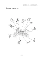
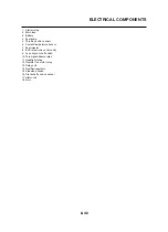
Page 366: ...8 39 ELECTRICAL COMPONENTS EAS27970 ELECTRICAL COMPONENTS ...
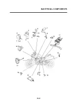
Page 368: ...8 41 ELECTRICAL COMPONENTS ...
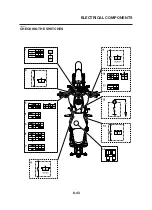
Page 370: ...8 43 ELECTRICAL COMPONENTS EAS27980 CHECKING THE SWITCHES ...
Page 389: ......
Page 391: ......
Page 397: ...COLOR CODE ...
Page 398: ......
Page 399: ...YAMAHA MOTOR ITALIA S P A ...
Page 400: ...MT 03 2006 WIRING DIAGRAM ...


