


8-46
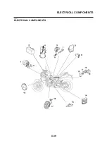
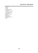
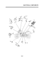
ELECTRICAL COMPONENTS
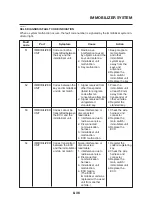
EAS27990
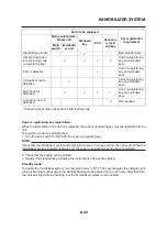
CHECKING THE BULBS AND BULB
SOCKETS
NOTE:
Do not check any of the lights that use LEDs.
Check each bulb and bulb socket for damage
or wear, proper connections, and also for conti-
nuity between the terminals.
Damage/wear
→
Repair or replace the bulb,
bulb socket or both.
Improperly connected
→
Properly connect.
No continuity
→
Repair or replace the bulb, bulb
socket or both.
Types of bulbs
The bulbs used on this vehicle are shown in the
following illustration.
• Bulbs “a” and “b” are used for the headlights
and usually use a bulb holder that must be
detached before removing the bulb. The ma-
jority of these types of bulbs can be removed
from their respective socket by turning them
counterclockwise.
• Bulbs “c” are used for turn signal and
tail/brake lights and can be removed from the
socket by pushing and turning the bulb coun-
terclockwise.
• Bulbs “d” and “e” are used for meter and indi-
cator lights and can be removed from their re-
spective socket by carefully pulling them out.
Checking the condition of the bulbs
The following procedure applies to all of the
bulbs.
1. Remove:
• Bulb
WARNING
Since headlight bulbs get extremely hot,
keep flammable products and your hands
away from them until they have cooled
down.
CAUTION:
•
Be sure to hold the socket firmly when re-
moving the bulb. Never pull the lead, oth-
erwise it may be pulled out of the terminal
in the coupler.
•
Avoid touching the glass part of a head-
light bulb to keep it free from oil, otherwise
the transparency of the glass, the life of
the bulb, and the luminous flux will be ad-
versely affected. If a headlight bulb gets
soiled, thoroughly clean it with a cloth
moistened with alcohol or lacquer thinner.
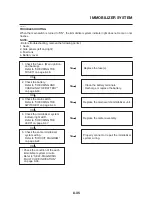
2. Check:
• Bulb (for continuity) (with the pocket tester)
No continuity
→
Replace.
Pocket tester
90890-03112
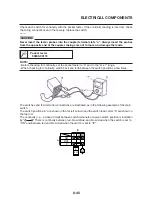
NOTE:
Before checking for continuity, set the pocket
tester to “0” and to the “Ω x 1” range.
Check each bulb and bulb socket for damage
a. Connect the positive tester probe to terminal
“1” and the negative tester probe to terminal
“2”, and check the continuity.
b. Connect the positive tester probe to terminal
“1” and the negative tester probe to terminal
“3”, and check the continuity.
c. If either of the readings indicate no continu-
ity, replace the bulb.
▼▼▼▼▼▼▼▼▼▼▼▼▼▼▼▼▼▼▼▼▼▼▼▼▼▼▼▼▼▼▼▼
▼▼▼▼▼▼▼▼▼▼▼▼▼▼▼▼▼▼▼▼▼▼▼▼▼▼▼▼▼▼▼▼
Summary of Contents for MT-03
Page 7: ......
Page 9: ......
Page 25: ......
Page 53: ...2 28 COOLING SYSTEM DIAGRAMS 1 2 3 4 5 6 7 8 9 5 10 11 A B C ...
Page 56: ...2 31 LUBRICATION CHART Pressure feed Splashed scavenge ...
Page 57: ...2 32 LUBRICATION DIAGRAMS LUBRICATION DIAGRAMS A A 1 3 2 2 4 A A A A ...
Page 59: ...2 34 LUBRICATION DIAGRAMS A A A A 3 1 2 3 4 ...
Page 60: ...2 35 LUBRICATION DIAGRAMS 1 Oil delivery pipe 2 2 Oil delivery pipe 1 3 Oil filter 4 Oil pump ...
Page 61: ...2 36 LUBRICATION DIAGRAMS 1 7 2 3 4 5 6 A ...
Page 63: ...2 38 LUBRICATION DIAGRAMS 1 6 5 4 3 2 ...
Page 65: ...2 40 CABLE ROUTING CABLE ROUTING ...
Page 67: ...2 42 CABLE ROUTING ...
Page 69: ...2 44 CABLE ROUTING ...
Page 71: ...2 46 CABLE ROUTING ...
Page 73: ...2 48 CABLE ROUTING ...
Page 75: ...2 50 CABLE ROUTING ...
Page 77: ...2 52 CABLE ROUTING ...
Page 79: ...2 54 CABLE ROUTING ...
Page 81: ...2 56 CABLE ROUTING ...
Page 83: ...2 58 CABLE ROUTING ...
Page 85: ...2 60 CABLE ROUTING ...
Page 87: ......
Page 121: ......
Page 177: ...4 54 FRONT FORK WARNING Make sure the brake hoses are routed prop erly ...
Page 271: ......
Page 273: ......
Page 287: ......
Page 325: ......
Page 339: ...8 12 CHARGING SYSTEM 2 A C magneto 5 Rectifier regulator 7 Battery 8 Main fuse ...
Page 341: ...8 14 CHARGING SYSTEM ...
Page 355: ...8 28 COOLING SYSTEM ...
Page 365: ...8 38 IMMOBILIZER SYSTEM ...
Page 366: ...8 39 ELECTRICAL COMPONENTS EAS27970 ELECTRICAL COMPONENTS ...
Page 368: ...8 41 ELECTRICAL COMPONENTS ...
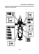
Page 370: ...8 43 ELECTRICAL COMPONENTS EAS27980 CHECKING THE SWITCHES ...
Page 389: ......
Page 391: ......
Page 397: ...COLOR CODE ...
Page 398: ......
Page 399: ...YAMAHA MOTOR ITALIA S P A ...
Page 400: ...MT 03 2006 WIRING DIAGRAM ...