


5-23
VALVES AND VALVE SPRINGS
3. Eliminate:
• Carbon deposits
(from the valve face and valve seat)
4. Check:
• Valve face
Pitting/wear •Grind the valve face.
• Valve stem end
Mushroom shape or diameter larger than
the body of the valve stem
→
Replace the
valve.
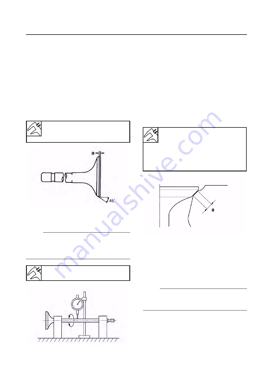
5. Measure:
• Valve margin thickness “a”
Out of specification
→
Replace the valve.
Valve margin thickness
0.80-1.20 mm
(0.0315-0.0472 in)
6. Measure:
• Valve stem runout
Out of specification
→
Replace the valve.
NOTE:
• When installing a new valve, always replace
the valve guide.
• If the valve is removed or replaced, always re-
place the valve stem seal.
Valve stem runout
0.010 mm (0.0004 in)
EAS00240
CHECKING THE VALVE SEATS
The following procedure applies to all of the
valves and valve seats.
1. Eliminate:
• Carbon deposits
(from the valve face and valve seat)
2. Check:
• Valve seat
Pitting/wear
→
Replace the cylinder head.
3. Measure:
• Valve seat width “a”
Out of specification
→
Replace the cylinder
head.
Valve seat width
Intake
1.00-1.20 mm
(0.0394-0.0472 in)
Exhaust
1.00-1.20 mm
(0.0394-0.0472 in)
▼▼▼▼▼▼▼▼▼▼▼▼▼▼▼▼▼▼▼▼▼▼▼▼▼▼▼▼▼▼▼▼
a. Apply Mechanic’s blueing dye (Dykem) onto
the valve face.
b. Install the valve into the cylinder head.
c. Press the valve through the valve guide and
onto the valve seat to make a clear impres-
sion.
d. Measure the valve seat width.
NOTE:
Where the valve seat and valve face contacted
one another, the blueing will have been re-
moved.
▼▼▼▼▼▼▼▼▼▼▼▼▼▼▼▼▼▼▼▼▼▼▼▼▼▼▼▼▼▼▼▼
Summary of Contents for MT-03
Page 7: ......
Page 9: ......
Page 25: ......
Page 53: ...2 28 COOLING SYSTEM DIAGRAMS 1 2 3 4 5 6 7 8 9 5 10 11 A B C ...
Page 56: ...2 31 LUBRICATION CHART Pressure feed Splashed scavenge ...
Page 57: ...2 32 LUBRICATION DIAGRAMS LUBRICATION DIAGRAMS A A 1 3 2 2 4 A A A A ...
Page 59: ...2 34 LUBRICATION DIAGRAMS A A A A 3 1 2 3 4 ...
Page 60: ...2 35 LUBRICATION DIAGRAMS 1 Oil delivery pipe 2 2 Oil delivery pipe 1 3 Oil filter 4 Oil pump ...
Page 61: ...2 36 LUBRICATION DIAGRAMS 1 7 2 3 4 5 6 A ...
Page 63: ...2 38 LUBRICATION DIAGRAMS 1 6 5 4 3 2 ...
Page 65: ...2 40 CABLE ROUTING CABLE ROUTING ...
Page 67: ...2 42 CABLE ROUTING ...
Page 69: ...2 44 CABLE ROUTING ...
Page 71: ...2 46 CABLE ROUTING ...
Page 73: ...2 48 CABLE ROUTING ...
Page 75: ...2 50 CABLE ROUTING ...
Page 77: ...2 52 CABLE ROUTING ...
Page 79: ...2 54 CABLE ROUTING ...
Page 81: ...2 56 CABLE ROUTING ...
Page 83: ...2 58 CABLE ROUTING ...
Page 85: ...2 60 CABLE ROUTING ...
Page 87: ......
Page 121: ......
Page 177: ...4 54 FRONT FORK WARNING Make sure the brake hoses are routed prop erly ...
Page 271: ......
Page 273: ......
Page 287: ......
Page 325: ......
Page 339: ...8 12 CHARGING SYSTEM 2 A C magneto 5 Rectifier regulator 7 Battery 8 Main fuse ...
Page 341: ...8 14 CHARGING SYSTEM ...
Page 355: ...8 28 COOLING SYSTEM ...
Page 365: ...8 38 IMMOBILIZER SYSTEM ...
Page 366: ...8 39 ELECTRICAL COMPONENTS EAS27970 ELECTRICAL COMPONENTS ...
Page 368: ...8 41 ELECTRICAL COMPONENTS ...
Page 370: ...8 43 ELECTRICAL COMPONENTS EAS27980 CHECKING THE SWITCHES ...
Page 389: ......
Page 391: ......
Page 397: ...COLOR CODE ...
Page 398: ......
Page 399: ...YAMAHA MOTOR ITALIA S P A ...
Page 400: ...MT 03 2006 WIRING DIAGRAM ...


