


7-28
FUEL INJECTION SYSTEM
TROUBLESHOOTING DETAILS
This section describes the countermeasures per fault code number displayed on the FI diagnostic
tool. Check and service the items or components that are the probable cause of the malfunction fol-
lowing the order given.
After the check and service of the malfunctioning part has been completed, reset the FI diagnostic
tool display according to the “Reinstatement method”.
Fault code No.:
Fault code number displayed on the FI diagnostic tool when the engine failed to work normally.
Refer to “Diagnostic code table”.
Diagnostic code No.:
Diagnostic code number to be used when the diagnostic mode is operated. Refer to “DIAGNOS-
TIC MODE”.
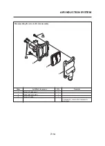
Fault code No.
12
Symptom
No normal signals are received from the crankshaft position sensor.
Used diagnostic code No. – –
Order
Item/components
Check or maintenance job
Restore method
1
Crankshaft position sensor installa-
tion
Check the sensor for looseness or pinching.
Reinstated by crank-
ing the engine.
2
Coupler connections
Crankshaft position sensor cou-
pler
ECU coupler
Check the couplers for any pins that may have
pulled out.
Check that the couplers are securely locked.
If necessary, repair the coupler or securely con-
nect it.
3
Open or short circuit in the wire har-
ness
Repair or replace if there is an open or short cir-
cuit between the wire harnesses.
Gray - Gray
Green/White - Black/Blue
4
Defective crankshaft position sen-
sor
Replace the sensor if it is defective.
Refer to “IGNITION SYSTEM” on page 8-1.
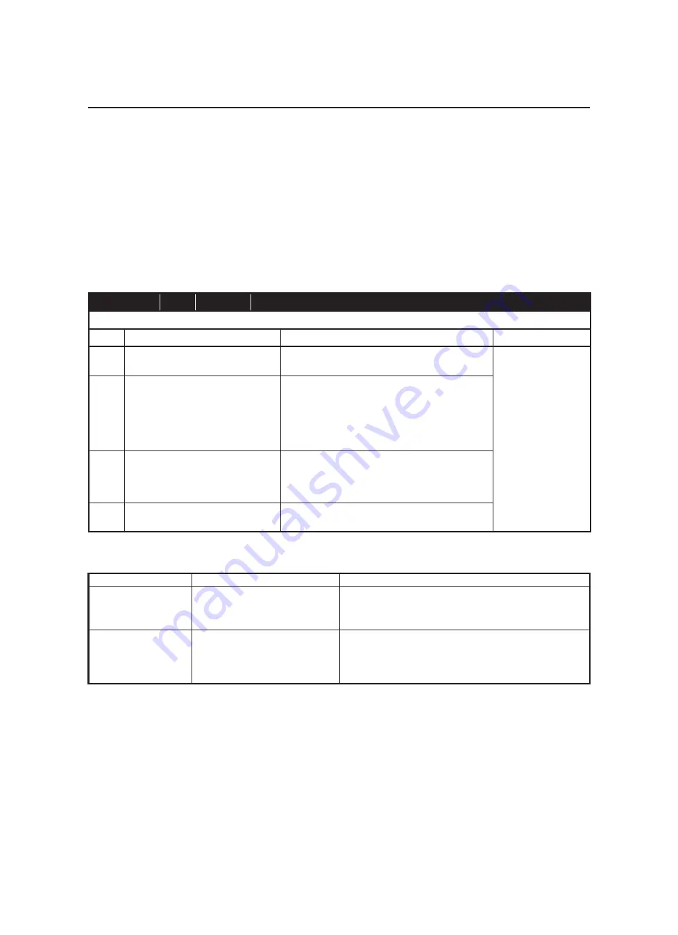
Waiting for connection....
No signals are received from the
ECU.
• Improper connection in connecting lead.
• The main switch is OFF position.
• Malfunction in FI diagnostic tool.
• Malfunction in ECU.
ERROR 4
Commands from the FI diagnostic
tool are not accepted by the ECU.
• Turn the main switch to “OFF” once, and then set the FI diagnos-
tic tool to CO adjustment mode or diagnostic mode.
• Vehicle battery is insufficiently charged.
• Malfunction in FI diagnostic tool.
• Malfunction in ECU.
LCD Display
Symptom
Probable cause of malfunction
Communication error with the FI diagnostic tool
Summary of Contents for MT-03
Page 7: ......
Page 9: ......
Page 25: ......
Page 53: ...2 28 COOLING SYSTEM DIAGRAMS 1 2 3 4 5 6 7 8 9 5 10 11 A B C ...
Page 56: ...2 31 LUBRICATION CHART Pressure feed Splashed scavenge ...
Page 57: ...2 32 LUBRICATION DIAGRAMS LUBRICATION DIAGRAMS A A 1 3 2 2 4 A A A A ...
Page 59: ...2 34 LUBRICATION DIAGRAMS A A A A 3 1 2 3 4 ...
Page 60: ...2 35 LUBRICATION DIAGRAMS 1 Oil delivery pipe 2 2 Oil delivery pipe 1 3 Oil filter 4 Oil pump ...
Page 61: ...2 36 LUBRICATION DIAGRAMS 1 7 2 3 4 5 6 A ...
Page 63: ...2 38 LUBRICATION DIAGRAMS 1 6 5 4 3 2 ...
Page 65: ...2 40 CABLE ROUTING CABLE ROUTING ...
Page 67: ...2 42 CABLE ROUTING ...
Page 69: ...2 44 CABLE ROUTING ...
Page 71: ...2 46 CABLE ROUTING ...
Page 73: ...2 48 CABLE ROUTING ...
Page 75: ...2 50 CABLE ROUTING ...
Page 77: ...2 52 CABLE ROUTING ...
Page 79: ...2 54 CABLE ROUTING ...
Page 81: ...2 56 CABLE ROUTING ...
Page 83: ...2 58 CABLE ROUTING ...
Page 85: ...2 60 CABLE ROUTING ...
Page 87: ......
Page 121: ......
Page 177: ...4 54 FRONT FORK WARNING Make sure the brake hoses are routed prop erly ...
Page 271: ......
Page 273: ......
Page 287: ......
Page 325: ......
Page 339: ...8 12 CHARGING SYSTEM 2 A C magneto 5 Rectifier regulator 7 Battery 8 Main fuse ...
Page 341: ...8 14 CHARGING SYSTEM ...
Page 355: ...8 28 COOLING SYSTEM ...
Page 365: ...8 38 IMMOBILIZER SYSTEM ...
Page 366: ...8 39 ELECTRICAL COMPONENTS EAS27970 ELECTRICAL COMPONENTS ...
Page 368: ...8 41 ELECTRICAL COMPONENTS ...
Page 370: ...8 43 ELECTRICAL COMPONENTS EAS27980 CHECKING THE SWITCHES ...
Page 389: ......
Page 391: ......
Page 397: ...COLOR CODE ...
Page 398: ......
Page 399: ...YAMAHA MOTOR ITALIA S P A ...
Page 400: ...MT 03 2006 WIRING DIAGRAM ...


