


3-4
ENGINE
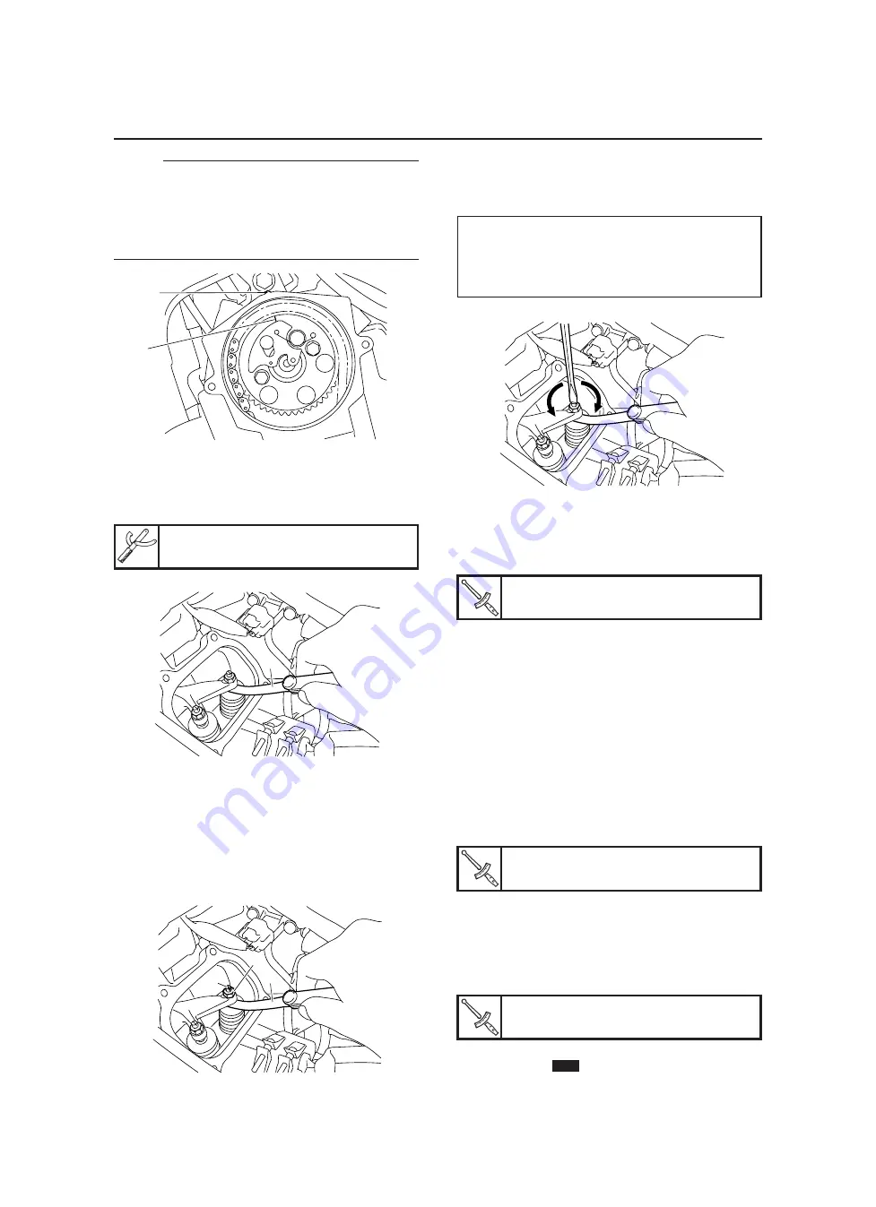
NOTE:
To position the piston at top dead center (TDC)
on the compression stroke, align the “I” mark
“c” on the camshaft sprocket with the stationary
pointer “d” on the cylinder head, as shown in
the illustration.
c. Measure the valve clearance with a thick-
ness gauge “1”.
Out of specification
→
Adjust.
d
c
Thickness gauge
90890-03079
1
▼▼▼▼▼▼▼▼▼▼▼▼▼▼▼▼▼▼▼▼▼▼▼▼▼▼▼▼▼▼▼▼
7. Adjust:
• Valve clearance
a. Loosen the locknut “1”.
b. Insert a thickness gauge “2” between the
end of the adjusting screw and the valve tip.
1
2
3
▼▼▼▼▼▼▼▼▼▼▼▼▼▼▼▼▼▼▼▼▼▼▼▼▼▼▼▼▼▼▼▼
c. Turn the adjusting screw “3” in direction “a”
or “b” until the specified valve clearance is
obtained.
Direction “a”
Valve clearance is increased.
Direction “b”
Valve clearance is decreased.
d. Hold the adjusting screw to prevent it from
moving and tighten the locknut to the speci-
fied torque.
a
b
e. Measure the valve clearance again.
f. If the valve clearance is still out of specifica-
tion, repeat all of the valve clearance adjust-
ment steps until the specified clearance is
obtained.
Locknut
14 Nm (1.4 m·kg, 10 ft·lb)
▼▼▼▼▼▼▼▼▼▼▼▼▼▼▼▼▼▼▼▼▼▼▼▼▼▼▼▼▼▼▼▼
8. Install:
• Timing mark accessing screw
• Crankshaft end accessing screw
9. Install:
• Spark plug
10.Connect:
• Spark plug cap
11.Install:
• Camshaft sprocket cover
• O-rings “1”
New
Spark plug
13 Nm (1.3 m·kg, 9.4 ft·lb)
Camshaft sprocket cover bolt
10 Nm (1.0 m·kg, 7.2 ft·lb)
Summary of Contents for MT-03
Page 7: ......
Page 9: ......
Page 25: ......
Page 53: ...2 28 COOLING SYSTEM DIAGRAMS 1 2 3 4 5 6 7 8 9 5 10 11 A B C ...
Page 56: ...2 31 LUBRICATION CHART Pressure feed Splashed scavenge ...
Page 57: ...2 32 LUBRICATION DIAGRAMS LUBRICATION DIAGRAMS A A 1 3 2 2 4 A A A A ...
Page 59: ...2 34 LUBRICATION DIAGRAMS A A A A 3 1 2 3 4 ...
Page 60: ...2 35 LUBRICATION DIAGRAMS 1 Oil delivery pipe 2 2 Oil delivery pipe 1 3 Oil filter 4 Oil pump ...
Page 61: ...2 36 LUBRICATION DIAGRAMS 1 7 2 3 4 5 6 A ...
Page 63: ...2 38 LUBRICATION DIAGRAMS 1 6 5 4 3 2 ...
Page 65: ...2 40 CABLE ROUTING CABLE ROUTING ...
Page 67: ...2 42 CABLE ROUTING ...
Page 69: ...2 44 CABLE ROUTING ...
Page 71: ...2 46 CABLE ROUTING ...
Page 73: ...2 48 CABLE ROUTING ...
Page 75: ...2 50 CABLE ROUTING ...
Page 77: ...2 52 CABLE ROUTING ...
Page 79: ...2 54 CABLE ROUTING ...
Page 81: ...2 56 CABLE ROUTING ...
Page 83: ...2 58 CABLE ROUTING ...
Page 85: ...2 60 CABLE ROUTING ...
Page 87: ......
Page 121: ......
Page 177: ...4 54 FRONT FORK WARNING Make sure the brake hoses are routed prop erly ...
Page 271: ......
Page 273: ......
Page 287: ......
Page 325: ......
Page 339: ...8 12 CHARGING SYSTEM 2 A C magneto 5 Rectifier regulator 7 Battery 8 Main fuse ...
Page 341: ...8 14 CHARGING SYSTEM ...
Page 355: ...8 28 COOLING SYSTEM ...
Page 365: ...8 38 IMMOBILIZER SYSTEM ...
Page 366: ...8 39 ELECTRICAL COMPONENTS EAS27970 ELECTRICAL COMPONENTS ...
Page 368: ...8 41 ELECTRICAL COMPONENTS ...
Page 370: ...8 43 ELECTRICAL COMPONENTS EAS27980 CHECKING THE SWITCHES ...
Page 389: ......
Page 391: ......
Page 397: ...COLOR CODE ...
Page 398: ......
Page 399: ...YAMAHA MOTOR ITALIA S P A ...
Page 400: ...MT 03 2006 WIRING DIAGRAM ...


