


8-45
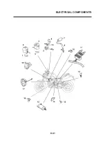
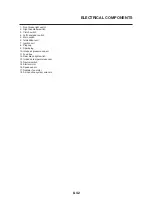
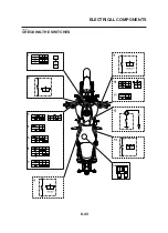
ELECTRICAL COMPONENTS
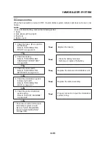
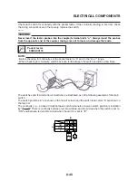
Check each switch for continuity with the pocket tester. If the continuity reading is incorrect, check
the wiring connections and if necessary, replace the switch.
ECA14370
CAUTION:
Never insert the tester probes into the coupler terminal slots “a”. Always insert the probes
from the opposite end of the coupler, taking care not to loosen or damage the leads.
Pocket tester
90890-03112
NOTE:
• Before checking for continuity, set the pocket tester to “0” and to the “Ω x 1” range.
• When checking for continuity, switch back and forth between the switch positions a few times.
The switches and their terminal connections are illustrated as in the following example of the main
switch.
The switch positions “a” are shown in the far left column and the switch lead colors “b” are shown in
the top row.
The continuity (i. e., a closed circuit) between switch terminals at a given switch position is indication
by “ ” There is continuity between red, brown/blue, and brown/red when the switch is set to
“ON” and between red and brown/red when the switch is set to “
F
”.
ON
R Br/L Br/R
OFF
P
Br
/
R
R
Br
/
L
a
b
Summary of Contents for MT-03
Page 7: ......
Page 9: ......
Page 25: ......
Page 53: ...2 28 COOLING SYSTEM DIAGRAMS 1 2 3 4 5 6 7 8 9 5 10 11 A B C ...
Page 56: ...2 31 LUBRICATION CHART Pressure feed Splashed scavenge ...
Page 57: ...2 32 LUBRICATION DIAGRAMS LUBRICATION DIAGRAMS A A 1 3 2 2 4 A A A A ...
Page 59: ...2 34 LUBRICATION DIAGRAMS A A A A 3 1 2 3 4 ...
Page 60: ...2 35 LUBRICATION DIAGRAMS 1 Oil delivery pipe 2 2 Oil delivery pipe 1 3 Oil filter 4 Oil pump ...
Page 61: ...2 36 LUBRICATION DIAGRAMS 1 7 2 3 4 5 6 A ...
Page 63: ...2 38 LUBRICATION DIAGRAMS 1 6 5 4 3 2 ...
Page 65: ...2 40 CABLE ROUTING CABLE ROUTING ...
Page 67: ...2 42 CABLE ROUTING ...
Page 69: ...2 44 CABLE ROUTING ...
Page 71: ...2 46 CABLE ROUTING ...
Page 73: ...2 48 CABLE ROUTING ...
Page 75: ...2 50 CABLE ROUTING ...
Page 77: ...2 52 CABLE ROUTING ...
Page 79: ...2 54 CABLE ROUTING ...
Page 81: ...2 56 CABLE ROUTING ...
Page 83: ...2 58 CABLE ROUTING ...
Page 85: ...2 60 CABLE ROUTING ...
Page 87: ......
Page 121: ......
Page 177: ...4 54 FRONT FORK WARNING Make sure the brake hoses are routed prop erly ...
Page 271: ......
Page 273: ......
Page 287: ......
Page 325: ......
Page 339: ...8 12 CHARGING SYSTEM 2 A C magneto 5 Rectifier regulator 7 Battery 8 Main fuse ...
Page 341: ...8 14 CHARGING SYSTEM ...
Page 355: ...8 28 COOLING SYSTEM ...
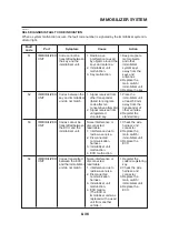
Page 365: ...8 38 IMMOBILIZER SYSTEM ...
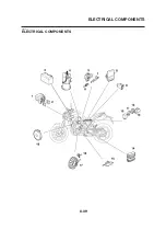
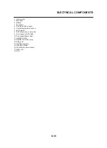
Page 366: ...8 39 ELECTRICAL COMPONENTS EAS27970 ELECTRICAL COMPONENTS ...
Page 368: ...8 41 ELECTRICAL COMPONENTS ...
Page 370: ...8 43 ELECTRICAL COMPONENTS EAS27980 CHECKING THE SWITCHES ...
Page 389: ......
Page 391: ......
Page 397: ...COLOR CODE ...
Page 398: ......
Page 399: ...YAMAHA MOTOR ITALIA S P A ...
Page 400: ...MT 03 2006 WIRING DIAGRAM ...