


3 - 11
CHK
ADJ
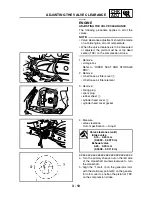
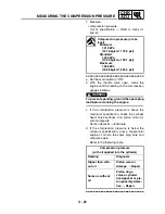
ADJUSTING THE VALVE CLEARANCE
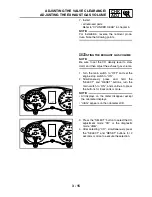
NOTE:
_
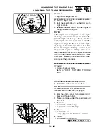
• TDC on the compression stroke can be
found when the camshaft lobes are turned
away from each other.
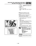
• In order to be sure that the piston is at TDC,
the punch marks
c
on the intake camshaft
sprocket and the punch mark
d
on the
exhaust camshaft sprocket must align with
the cylinder head mating surface as shown in
the illustration.
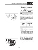
c. Measure the valve clearance with a thick-
ness gauge
1
.
NOTE:
_
If the valve clearance is incorrect, record the
measured reading.
▲▲▲
▲
▲ ▲▲▲
▲
▲ ▲▲▲
▲
▲ ▲▲▲
▲
▲ ▲▲▲
▲
▲ ▲▲▲
▲
▲▲▲
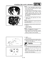
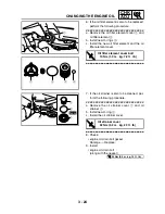
5. Remove:
• intake camshaft
• exhaust camshaft
NOTE:
_
• Refer to “CAMSHAFTS” in chapter 5.
• When removing the timing chain and cam-
shafts, fasten a wire to the timing chain to
retrieve it if it falls into the crankcase.
c
d
1
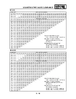
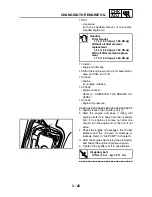
6. Adjust:
• valve clearance
▼▼▼
▼
▼ ▼▼▼
▼
▼ ▼▼▼
▼
▼ ▼▼▼
▼
▼ ▼▼▼
▼
▼ ▼▼▼
▼
▼▼▼
a. Remove the valve lifter
1
and the valve pad
2
with the valve lapper
3
.
NOTE:
_
• Cover the timing chain opening with a rag to
prevent the valve pad from falling into the
crankcase.
• Make a note of the position of each valve
lifter
1
and valve pad
2
so that they can be
installed in the correct place.
Valve lapper
90890-04101
Summary of Contents for 2004 YP400
Page 1: ...2004 YP400 S 5RU1 AE1 SERVICE MANUAL ...
Page 2: ......
Page 8: ......
Page 9: ...GEN INFO 1 ...
Page 11: ...GEN INFO ...
Page 28: ...SPEC 2 ...
Page 30: ...SPEC ...
Page 77: ...CHK ADJ 3 ...
Page 137: ......
Page 138: ...CHAS 4 ...
Page 210: ......
Page 211: ...ENG 5 ...
Page 286: ...COOL 6 ...
Page 288: ...COOL ...
Page 299: ...FI 7 ...
Page 301: ...FI ...
Page 342: ...ELEC 8 ...
Page 378: ...8 34 ELEC LIGHTING SYSTEM ...
Page 404: ......
Page 405: ...TRBL SHTG 9 ...
Page 415: ......
Page 416: ...YAMAHA MOTOR CO LTD 2500 SHINGAI IWATA SHIZUOKA JAPAN ...