

7 - 24
FI
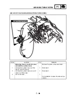
FUEL INJECTION SYSTEM
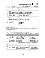
Fault code No.
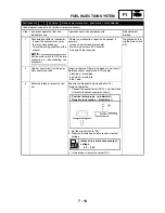
Er-2
Symptom
No signals are received from the ECU within the specified duration.
Used diagnostic code No. – –
Order
Inspection operation item and
probable cause
Operation item and countermeasure
Reinstatement
method
1
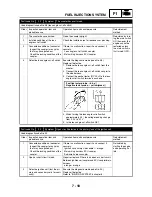
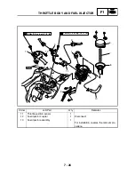
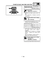
Connected condition of connector
Inspect the coupler for any pins
that may have pulled out.
Check the locking condition of the
coupler.
If there is a malfunction, repair it and connect it
securely.
Main wiring harness ECU coupler
Sub-wire harness coupler
Reinstated if nor-
mal signal is
received from the
ECU when the
main switch is set
to ON.
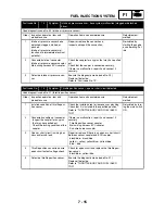
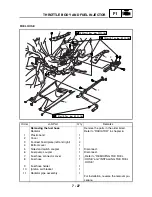
2
Open or short circuit in wiring har-
ness and/or sub lead.
Repair or replace if there is an open or short circuit.
Between meter coupler and ECU coupler
yellow/blue – yellow/blue
3
Malfunction in meter
Replace the meter.
4
Malfunction in ECU
Replace the ECU.
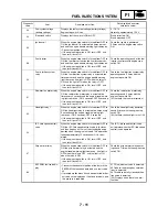
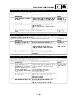
Fault code No.
Er-3
Symptom
Data from the ECU cannot be received correctly.
Used diagnostic code No. – –
Order
Inspection operation item and
probable cause
Operation item and countermeasure
Reinstatement
method
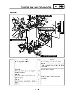
1
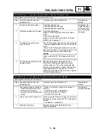
Connected condition of connector
Inspect the coupler for any pins
that may have pulled out.
Check the locking condition of the
coupler.
If there is a malfunction, repair it and connect it
securely.
Main wiring harness ECU coupler
Sub-wire harness coupler
Reinstated if nor-
mal signal is
received from the
ECU when the
main switch is set
to ON.
2
Open or short circuit in wiring har-
ness and/or sub lead.
Repair or replace if there is an open or short circuit.
Between meter coupler and ECU coupler
yellow/blue – yellow/blue
3
Malfunction in meter
Replace the meter.
4
Malfunction in ECU
Replace the ECU.
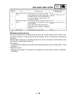
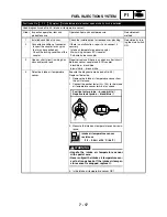
Fault code No.
Er-4
Symptom
Non-registered data has been received from the meter.
Used diagnostic code No. – –
Order
Inspection operation item and
probable cause
Operation item and countermeasure
Reinstatement
method
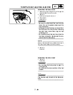
1
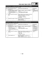
Connected condition of connector
Inspect the coupler for any pins
that may have pulled out.
Check the locking condition of the
coupler.
If there is a malfunction, repair it and connect it
securely.
Main wiring harness ECU coupler
Sub-wire harness coupler
Reinstated if nor-
mal signal is
received from the
ECU when the
main switch is set
to ON.
2
Open or short circuit in wiring har-
ness and/or sub lead.
Repair or replace if there is an open or short circuit.
Between meter coupler and ECU coupler
yellow/blue – yellow/blue
3
Malfunction in meter
Replace the meter.
4
Malfunction in ECU
Replace the ECU.
Summary of Contents for 2004 YP400
Page 1: ...2004 YP400 S 5RU1 AE1 SERVICE MANUAL ...
Page 2: ......
Page 8: ......
Page 9: ...GEN INFO 1 ...
Page 11: ...GEN INFO ...
Page 28: ...SPEC 2 ...
Page 30: ...SPEC ...
Page 77: ...CHK ADJ 3 ...
Page 137: ......
Page 138: ...CHAS 4 ...
Page 210: ......
Page 211: ...ENG 5 ...
Page 286: ...COOL 6 ...
Page 288: ...COOL ...
Page 299: ...FI 7 ...
Page 301: ...FI ...
Page 342: ...ELEC 8 ...
Page 378: ...8 34 ELEC LIGHTING SYSTEM ...
Page 404: ......
Page 405: ...TRBL SHTG 9 ...
Page 415: ......
Page 416: ...YAMAHA MOTOR CO LTD 2500 SHINGAI IWATA SHIZUOKA JAPAN ...