


8 - 12
–
+
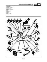
ELEC
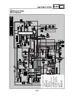
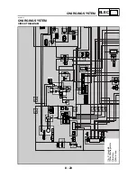
IGNITION SYSTEM
EAS00750
YES
NO
EAS00752
YES
NO
EAS00753
YES
NO
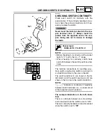
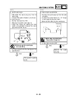
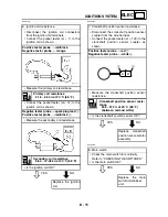
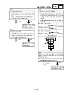
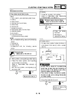
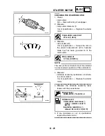
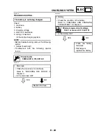
9. Engine stop switch
• Check the engine stop switch for continu-
ity.
Refer to “CHECKING THE SWITCHES”.
• Is the engine stop switch OK?
Replace the right
handlebar switch.
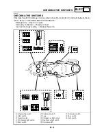
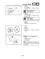
10.Sidestand switch
• Check the sidestand switch for continuity.
Refer to “CHECKING THE SWITCHES”.
• Is the sidestand switch OK?
Replace the side-
stand switch.
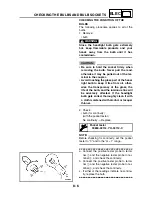
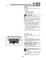
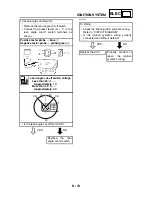
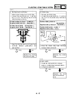
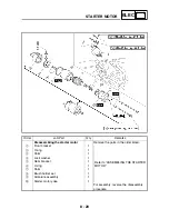
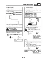
11.Starting circuit cut-off relay
• Remove the starting circuit cut-off relay.
• Connect the pocket tester (
Ω
×
1) to the
starting circuit cut-off relay terminals as
shown.
• Check the starting circuit cut-off relay for
continuity.
Positive tester probe
→
blue/yellow
1
Negative tester probe
→
red/black
2
Continuity
Positive tester probe
→
red/black
2
Negative tester probe
→
blue/yellow
1
No
continuity
NOTE:
_
When you switch the positive and negative
tester probes, the readings in the above chart
will be reversed.
• Are the tester readings correct?
Replace the starting
circuit cut-off relay.
1
2
G
/
W
R
/
B
L
/
Y
G
/
Y
Summary of Contents for 2004 YP400
Page 1: ...2004 YP400 S 5RU1 AE1 SERVICE MANUAL ...
Page 2: ......
Page 8: ......
Page 9: ...GEN INFO 1 ...
Page 11: ...GEN INFO ...
Page 28: ...SPEC 2 ...
Page 30: ...SPEC ...
Page 77: ...CHK ADJ 3 ...
Page 137: ......
Page 138: ...CHAS 4 ...
Page 210: ......
Page 211: ...ENG 5 ...
Page 286: ...COOL 6 ...
Page 288: ...COOL ...
Page 299: ...FI 7 ...
Page 301: ...FI ...
Page 342: ...ELEC 8 ...
Page 378: ...8 34 ELEC LIGHTING SYSTEM ...
Page 404: ......
Page 405: ...TRBL SHTG 9 ...
Page 415: ......
Page 416: ...YAMAHA MOTOR CO LTD 2500 SHINGAI IWATA SHIZUOKA JAPAN ...