


2 - 31
SPEC
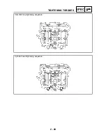
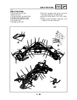
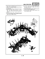
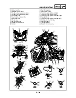
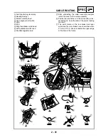
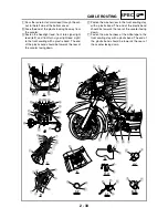
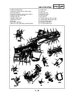
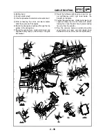
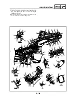
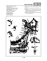
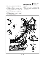
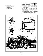
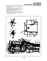
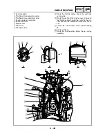
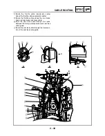
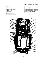
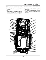
CABLE ROUTING
M
Fuel injection system relay
N
Headlight relay 1
O
Meter assembly lead
P
Lean angle cut-off switch
Q
Horn
R
ECU
S
Right handlebar switch lead
T
Left handlebar switch lead
U
Rectifier/regulator lead
È
After connecting the meter assembly coupler,
install the cover to the meter assembly.
É
Fasten the wire harness to the frame with a plas-
tic locking tie. Face the end of the plastic locking
tie down.
Ê
The paint marks on the rear brake lock lever
cable and the rear brake hose should be within
20 mm (0.79 in) above or below the upper edge
of the hole in the frame.
D
A
B
C
D
4
3
5
6
È
H
H
E
F
F
G
E
B
F-F
H-H
Ó
F-F
G
0
U
0
8
Ò
Ô
J
J
K
K
I
I
G
D
E
8
Ö
8
×
Õ
D
E
8
JKLM
F
Q
R
N
O
D
P
I
Ï
C
4
3
S
6
7
T
5
S
5
4
3
T
7
6
Ð
Ñ
A
I-I
J-J
K-K
B
E
C
1
2
7
8
É
Ë
Ê
É
Ì
Í
A
B
0 9
HG
G
Î
Summary of Contents for 2004 YP400
Page 1: ...2004 YP400 S 5RU1 AE1 SERVICE MANUAL ...
Page 2: ......
Page 8: ......
Page 9: ...GEN INFO 1 ...
Page 11: ...GEN INFO ...
Page 28: ...SPEC 2 ...
Page 30: ...SPEC ...
Page 77: ...CHK ADJ 3 ...
Page 137: ......
Page 138: ...CHAS 4 ...
Page 210: ......
Page 211: ...ENG 5 ...
Page 286: ...COOL 6 ...
Page 288: ...COOL ...
Page 299: ...FI 7 ...
Page 301: ...FI ...
Page 342: ...ELEC 8 ...
Page 378: ...8 34 ELEC LIGHTING SYSTEM ...
Page 404: ......
Page 405: ...TRBL SHTG 9 ...
Page 415: ......
Page 416: ...YAMAHA MOTOR CO LTD 2500 SHINGAI IWATA SHIZUOKA JAPAN ...