

7 - 10
FI
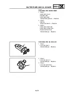
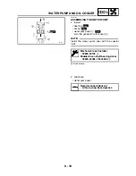
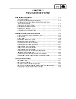
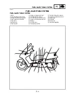
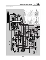
FUEL INJECTION SYSTEM
EAS00907
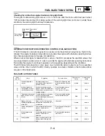
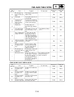
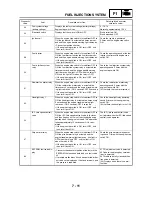
Diagnostic mode table
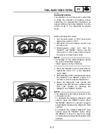
Switch the meter display from the regular mode to the diagnostic mode. To switch the display, refer
to “DIAGNOSTIC MODE”.
NOTE:
_
• Check the intake air temperature and coolant temperature as close as possible to the intake air
temperature sensor and the coolant temperature sensor respectively.
• If it is not possible to check the intake air temperature, use the ambient temperature as reference.
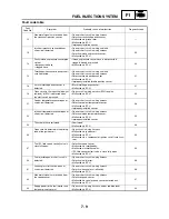
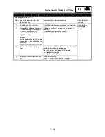
44
An error is detected while reading or
writing on EEPROM.
• Malfunction in ECU. (The CO adjustment value, code re-
registering key code, and throttle valve fully closed notifi-
cation value are not properly written on or read from the
internal memory.)
60
46
Power supply to the FI system is not
normal.
• Malfunction in charging system.
—
50
Faulty ECU memory. When this mal-
function is detected, the code number
might not appear on the meter.
• Malfunction in ECU. (The program and data are not
properly written on or read from the internal memory.)
—
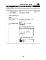
61
ISC (idle speed control) valve open or
short circuit is detected.
• Open or short circuit in wiring harness.
• Defective ISC (idle speed control) valve.
• Malfunction in ECU.
54
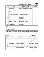
Er-1
No signals are received from the
ECU.
• Open or short circuit in wiring sub lead.
• Malfunction in meter.
• Malfunction in ECU.
—
Er-2
No signals are received from the ECU
within the specified duration.
• Improper connection in wiring sub lead.
• Malfunction in meter.
• Malfunction in ECU.
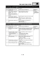
—
Er-3
Data from the ECU cannot be
received correctly.
• Improper connection in wiring sub lead.
• Malfunction in meter.
• Malfunction in ECU.
—
Er-4
Non-registered data has been
received from the meter.
• Improper connection in wiring sub lead.
• Malfunction in meter.
• Malfunction in ECU.
—
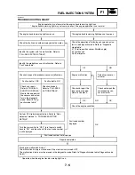
Diagnostic
code
Item
Description of action
Data displayed on meter
(reference value)
01
Throttle angle
Displays the throttle angle.
• Check with throttle fully closed.
• Check with throttle fully open.
0 ~ 125 degrees
• Fully closed position (15 ~ 16)
• Fully open position (97 ~ 102)
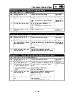
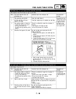
03
Pressure difference
(atmospheric pressure-
intake air pressure)
Displays the pressure difference (atmospheric pres-
sure-intake air pressure).
Engine stop switch is on.
• Generate the pressure difference by cranking the
engine with the starter, without actually starting the
engine.
When engine is stopped:
Atmospheric pressure 101.3 kPa
(760 mmHg, 30 inHg) when cranking
the engine with the start switch.
0 ~ 126 kPa (1.26 kgf/cm
2
, 17.9 psi)
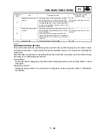
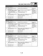
05
Intake air temperature
Displays the intake air temperature.
• Check the temperature in the air cleaner case.
Compare it to the value displayed on
the meter.
06
Coolant temperature
Displays the coolant temperature.
• Check the temperature of the coolant.
Compare it to the value displayed on
the meter.
07
Vehicle speed pulse
Displays the accumulation of the vehicle pulses that
are generated when the tire is spun.
(0 ~ 999; resets to 0 after 999)
OK if the numbers appear on the
meter.
08
Lean angle cut-off switch
Displays the lean angle cut-off switch values.
Upright: 0.4 ~ 1.4 V
Overturned: 3.8 ~ 4.2 V
Fault
Code No.
Symptom
Probable cause of malfunction
Diagnostic code
Summary of Contents for 2004 YP400
Page 1: ...2004 YP400 S 5RU1 AE1 SERVICE MANUAL ...
Page 2: ......
Page 8: ......
Page 9: ...GEN INFO 1 ...
Page 11: ...GEN INFO ...
Page 28: ...SPEC 2 ...
Page 30: ...SPEC ...
Page 77: ...CHK ADJ 3 ...
Page 137: ......
Page 138: ...CHAS 4 ...
Page 210: ......
Page 211: ...ENG 5 ...
Page 286: ...COOL 6 ...
Page 288: ...COOL ...
Page 299: ...FI 7 ...
Page 301: ...FI ...
Page 342: ...ELEC 8 ...
Page 378: ...8 34 ELEC LIGHTING SYSTEM ...
Page 404: ......
Page 405: ...TRBL SHTG 9 ...
Page 415: ......
Page 416: ...YAMAHA MOTOR CO LTD 2500 SHINGAI IWATA SHIZUOKA JAPAN ...