


2 - 19
SPEC
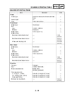
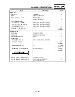
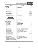
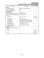
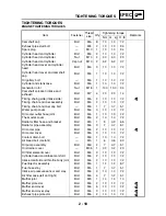
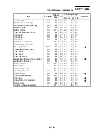
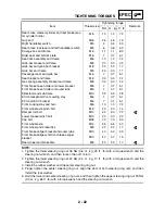
TIGHTENING TORQUES
Exhaust pipe
Nut
M8
2
20
2.0
14
Air induction system pipe
Bolt
M6
2
12
1.2
8.7
Air induction system pipe stay
Bolt
M6
1
7
0.7
5.1
Air cut-off valve
Bolt
M6
2
10
1.0
7.2
Muffler mount
Bolt
M10
3
53
5.3
38
V-belt case air duct 1 and 2
Bolt
M6
4
7
0.7
5.1
Crankcase
Bolt
M6
7
10
1.0
7.2
Crankcase
Bolt
M8
5
16
1.6
11
Crankcase
Bolt
M8
1
30
3.0
22
Cylinder head stud bolt
—
M10
4
13
1.3
9.4
Transmission oil drain bolt
—
M8
1
20
2.0
14
Bearing retainer
Screw
M6
1
10
1.0
7.2
LT
Transmission case cover
Bolt
M8
7
16
1.6
11
V-belt case
Bolt
M8
1
22
2.2
16
V-belt case
Bolt
M6
9
10
1.0
7.2
V-belt case cover
Bolt
M6
6
7
0.7
5.1
Generator rotor cover inner bracket
Bolt
M6
2
7
0.7
5.1
LT
Generator rotor cover
Bolt
M6
11
10
1.0
7.2
Primary sheave
Nut
M18
1
83
8.3
60
Timing plug
—
M16
1
8
0.8
5.8
Engine oil drain bolt
—
M12
1
20
2.0
14
Secondary sheave
Nut
M14
1
60
6.0
43
Starter clutch
Bolt
M8
6
30
3.0
22
LT
Clutch shoe assembly
Nut
M36
1
90
9.0
65
Stator coil
Bolt
M6
3
10
1.0
7.2
LT
Crankshaft position sensor
Bolt
M6
2
10
1.0
7.2
LT
Starter motor
Bolt
M6
2
12
1.2
8.7
Coolant temperature sensor
—
M12
1
18
1.8
13
Item
Fastener
Thread
size
Q’ty
Tightening torque
Remarks
Nm
m · kg ft · lb
Summary of Contents for 2004 YP400
Page 1: ...2004 YP400 S 5RU1 AE1 SERVICE MANUAL ...
Page 2: ......
Page 8: ......
Page 9: ...GEN INFO 1 ...
Page 11: ...GEN INFO ...
Page 28: ...SPEC 2 ...
Page 30: ...SPEC ...
Page 77: ...CHK ADJ 3 ...
Page 137: ......
Page 138: ...CHAS 4 ...
Page 210: ......
Page 211: ...ENG 5 ...
Page 286: ...COOL 6 ...
Page 288: ...COOL ...
Page 299: ...FI 7 ...
Page 301: ...FI ...
Page 342: ...ELEC 8 ...
Page 378: ...8 34 ELEC LIGHTING SYSTEM ...
Page 404: ......
Page 405: ...TRBL SHTG 9 ...
Page 415: ......
Page 416: ...YAMAHA MOTOR CO LTD 2500 SHINGAI IWATA SHIZUOKA JAPAN ...