


8 - 15
–
+
ELEC
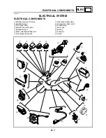
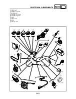
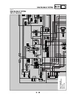
ELECTRIC STARTING SYSTEM
EAS00756
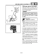
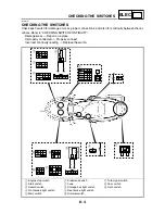
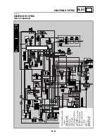
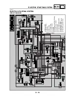
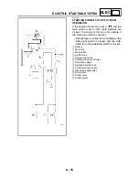
STARTING CIRCUIT CUT-OFF SYSTEM
OPERATION
If the engine stop switch is set to “
” and the
main switch is set to “ON” (both switches are
closed), the starter motor can only operate if
the following conditions are met:
• A brake lever is pulled to the handlebar (the
brake light switch is closed) and the side-
stand is up (the sidestand switch is closed).
1
Battery
2
Main fuse
3
Main switch
4
Ignition fuse
5
Engine stop switch
6
Starting circuit cut-off relay
7
Sidestand switch
8
Signaling system fuse
9
Front brake light switch
0
Rear brake light switch
A
Start switch
B
Starter relay
C
Starter motor
Summary of Contents for 2004 YP400
Page 1: ...2004 YP400 S 5RU1 AE1 SERVICE MANUAL ...
Page 2: ......
Page 8: ......
Page 9: ...GEN INFO 1 ...
Page 11: ...GEN INFO ...
Page 28: ...SPEC 2 ...
Page 30: ...SPEC ...
Page 77: ...CHK ADJ 3 ...
Page 137: ......
Page 138: ...CHAS 4 ...
Page 210: ......
Page 211: ...ENG 5 ...
Page 286: ...COOL 6 ...
Page 288: ...COOL ...
Page 299: ...FI 7 ...
Page 301: ...FI ...
Page 342: ...ELEC 8 ...
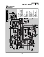
Page 378: ...8 34 ELEC LIGHTING SYSTEM ...
Page 404: ......
Page 405: ...TRBL SHTG 9 ...
Page 415: ......
Page 416: ...YAMAHA MOTOR CO LTD 2500 SHINGAI IWATA SHIZUOKA JAPAN ...