


5 - 19
ENG
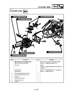
CYLINDER HEAD
EAS00222
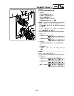
REMOVING THE CYLINDER HEAD
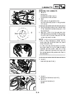
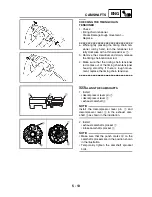
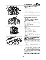
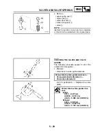
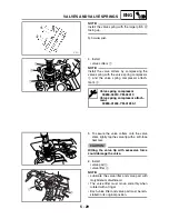
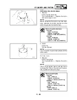
1. Remove:
• cylinder head nuts
NOTE:
_
• Loosen the cylinder head nuts in the proper
sequence as shown.
• Loosen each cylinder head nut 1/2 of a turn
at a time. After all of the cylinder head nuts
are fully loosened, remove them.
EAS00229
CHECKING THE CYLINDER HEAD
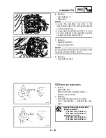
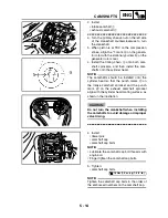
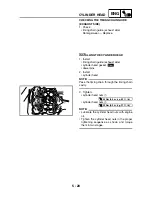
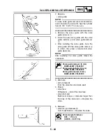
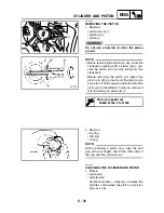
1. Eliminate:
• combustion chamber carbon deposits
(with a rounded scraper)
NOTE:
_
Do not use a sharp instrument to avoid damag-
ing or scratching:
• spark plug bore threads
• valve seats
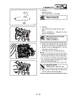
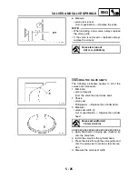
2. Check:
• cylinder head
Damage/scratches
→
Replace.
• cylinder head water jacket
Mineral deposits/rust
→
Eliminate.
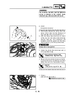
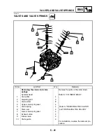
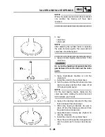
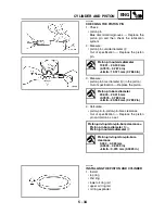
3. Measure:
• cylinder head warpage
Out of specification
→
Resurface the cylin-
der head.
▼▼▼
▼
▼ ▼▼▼
▼
▼ ▼▼▼
▼
▼ ▼▼▼
▼
▼ ▼▼▼
▼
▼ ▼▼▼
▼
▼▼▼
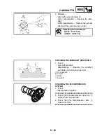
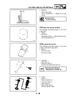
a. Place a straightedge
1
and a thickness
gauge
2
across the cylinder head.
b. Measure the warpage.
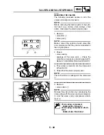
c. If the limit is exceeded, resurface the cylin-
der head as follows.
d. Place a 400 ~ 600 grit wet sandpaper on
the surface plate and resurface the cylinder
head using a figure-eight sanding pattern.
NOTE:
_
To ensure an even surface, rotate the cylinder
head several times.
▲▲▲
▲
▲ ▲▲▲
▲
▲ ▲▲▲
▲
▲ ▲▲▲
▲
▲ ▲▲▲
▲
▲ ▲▲▲
▲
▲▲▲
Maximum cylinder head warpage
0.05 mm (0.002 in)
2
3
4
1
2
1
Summary of Contents for 2004 YP400
Page 1: ...2004 YP400 S 5RU1 AE1 SERVICE MANUAL ...
Page 2: ......
Page 8: ......
Page 9: ...GEN INFO 1 ...
Page 11: ...GEN INFO ...
Page 28: ...SPEC 2 ...
Page 30: ...SPEC ...
Page 77: ...CHK ADJ 3 ...
Page 137: ......
Page 138: ...CHAS 4 ...
Page 210: ......
Page 211: ...ENG 5 ...
Page 286: ...COOL 6 ...
Page 288: ...COOL ...
Page 299: ...FI 7 ...
Page 301: ...FI ...
Page 342: ...ELEC 8 ...
Page 378: ...8 34 ELEC LIGHTING SYSTEM ...
Page 404: ......
Page 405: ...TRBL SHTG 9 ...
Page 415: ......
Page 416: ...YAMAHA MOTOR CO LTD 2500 SHINGAI IWATA SHIZUOKA JAPAN ...