


2 - 40
SPEC
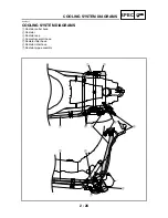
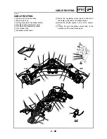
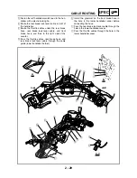
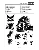
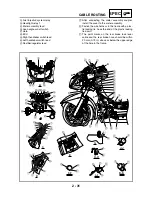
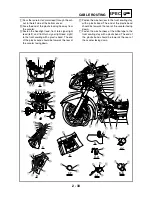
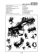
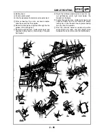
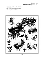
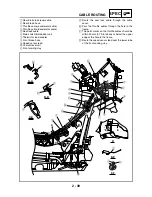
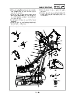
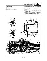
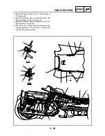
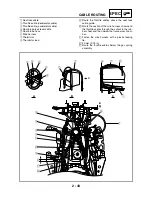
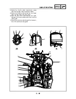
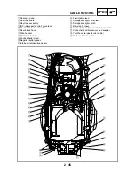
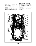
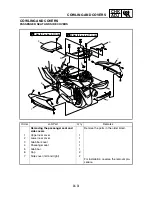
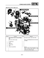
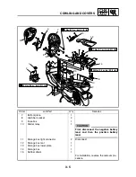
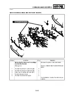
CABLE ROUTING
Ì
After connecting the main switch lead, immobi-
lizer unit lead, and speed sensor lead, put the
cover on the couplers.
Í
Route the front brake hose and speed sensor
lead through the guide on the front cowling stay
so that the speed sensor lead is towards the out-
side of the scooter.
Î
Hook the end of the cable cover in the hole in
the frame.
Ï
Attach the cable cover by installing the quick fas-
tener in the hole in the frame.
Ð
Hook the end of the cable cover in the hole in
the frame.
Ñ
Fasten a plastic band around the middle of the
coupler cover, and then face the end of the plas-
tic band down.
B
A-A
C-C
B-B
D
E-E
F-F
9
Í
Î
7
Ì
8
Ð
Ñ
6
5
3
4
É
È
2
0
A
1
Ë
5
5
Ï
Ê
5
C
B
A
A
C
D
E
E
F
F
Summary of Contents for 2004 YP400
Page 1: ...2004 YP400 S 5RU1 AE1 SERVICE MANUAL ...
Page 2: ......
Page 8: ......
Page 9: ...GEN INFO 1 ...
Page 11: ...GEN INFO ...
Page 28: ...SPEC 2 ...
Page 30: ...SPEC ...
Page 77: ...CHK ADJ 3 ...
Page 137: ......
Page 138: ...CHAS 4 ...
Page 210: ......
Page 211: ...ENG 5 ...
Page 286: ...COOL 6 ...
Page 288: ...COOL ...
Page 299: ...FI 7 ...
Page 301: ...FI ...
Page 342: ...ELEC 8 ...
Page 378: ...8 34 ELEC LIGHTING SYSTEM ...
Page 404: ......
Page 405: ...TRBL SHTG 9 ...
Page 415: ......
Page 416: ...YAMAHA MOTOR CO LTD 2500 SHINGAI IWATA SHIZUOKA JAPAN ...