


8 - 44
–
+
ELEC
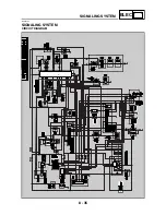
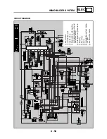
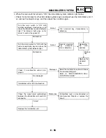
SIGNALING SYSTEM
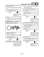
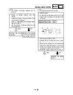
YES
NO
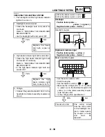
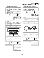
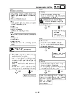
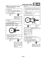
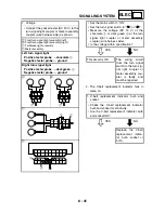
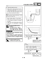
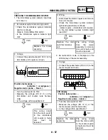
2. Voltage
• Connect the pocket tester (DC 20 V) to the
meter assembly coupler (wire harness
side) as shown.
Positive tester probe
→
yellow/blue
1
Negative tester probe
→
black
2
• Set the main switch to “ON”.
• Measure the voltage (DC 12 V) of yellow/
blue
1
on the meter assembly coupler
(wire harness side).
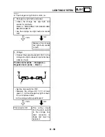
• Is the voltage within specification?
This circuit is OK.
Replace the meter
assembly.
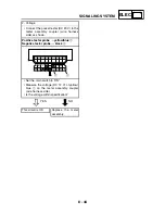
G
/
L
L
Y
/
L B
/
L Gy
B
Ch Dg
Y
R
/
W R
/
G G
2
1
Summary of Contents for 2004 YP400
Page 1: ...2004 YP400 S 5RU1 AE1 SERVICE MANUAL ...
Page 2: ......
Page 8: ......
Page 9: ...GEN INFO 1 ...
Page 11: ...GEN INFO ...
Page 28: ...SPEC 2 ...
Page 30: ...SPEC ...
Page 77: ...CHK ADJ 3 ...
Page 137: ......
Page 138: ...CHAS 4 ...
Page 210: ......
Page 211: ...ENG 5 ...
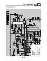
Page 286: ...COOL 6 ...
Page 288: ...COOL ...
Page 299: ...FI 7 ...
Page 301: ...FI ...
Page 342: ...ELEC 8 ...
Page 378: ...8 34 ELEC LIGHTING SYSTEM ...
Page 404: ......
Page 405: ...TRBL SHTG 9 ...
Page 415: ......
Page 416: ...YAMAHA MOTOR CO LTD 2500 SHINGAI IWATA SHIZUOKA JAPAN ...