

7 - 23
FI
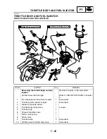
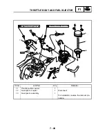
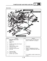
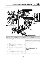
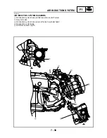
FUEL INJECTION SYSTEM
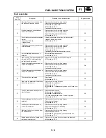
Fault code No.
50
Symptom
Faulty ECU memory. (When this malfunction is detected in the ECU, the fault
code number might not appear on the meter.)
Used diagnostic code No. – –
Order
Inspection operation item and
probable cause
Operation item and countermeasure
Reinstatement
method
1
Malfunction in ECU
Replace the ECU.
Reinstated by turn-
ing the main switch
ON.
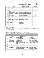
Fault code No.
61
Symptom
ISC (idle speed control) valve open or short circuit is detected.
Used diagnostic code No. – –
Order
Inspection operation item and
probable cause
Operation item and countermeasure
Reinstatement
method
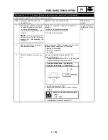
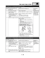
1
Connected condition of connector
Inspect the coupler for any pins
that may have pulled out.
Check the locking condition of the
coupler.
If there is a malfunction, repair it and connect it
securely.
ISC (idle speed control) valve coupler
Main wiring harness ECU coupler
Sub-wire harness coupler
Reinstated by set-
ting the main
switch to ON. The
ISC (idle speed
control) valve fully
closes, and then it
opens until it is at
the standby open-
ing position when
the engine is
started.
2
Open or short circuit in lead.
Repair or replace if there is an open or short circuit.
Between ISC (idle speed control) valve and ECU
coupler/main harness
pink – pink
light green – light green
gray – gray
sky blue – sky blue
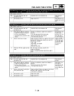
3
Detective ISC (idle speed control)
valve
Execute diagnostic mode (code No. 54)
Replace if defective.
Refer to “THROTTLE BODY AND FUEL INJEC-
TOR”.
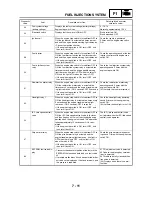
Fault code No.
Er-1
Symptom
No signals are received from the ECU.
Used diagnostic code No. – –
Order
Inspection operation item and
probable cause
Operation item and countermeasure
Reinstatement
method
1
Connected condition of connector
Inspect the coupler for any pins
that may have pulled out.
Check the locking condition of the
coupler.
If there is a malfunction, repair it and connect it
securely.
Main wiring harness ECU coupler
Sub-wire harness coupler
Reinstated if nor-
mal signal is
received from the
ECU when the
main switch is set
to ON.
2
Open or short circuit in wiring har-
ness and/or sub lead.
Repair or replace if there is an open or short circuit.
Between meter coupler and ECU coupler
yellow/blue – yellow/blue
3
Malfunction in meter
Replace the meter.
4
Malfunction in ECU
Replace the ECU.
Summary of Contents for 2004 YP400
Page 1: ...2004 YP400 S 5RU1 AE1 SERVICE MANUAL ...
Page 2: ......
Page 8: ......
Page 9: ...GEN INFO 1 ...
Page 11: ...GEN INFO ...
Page 28: ...SPEC 2 ...
Page 30: ...SPEC ...
Page 77: ...CHK ADJ 3 ...
Page 137: ......
Page 138: ...CHAS 4 ...
Page 210: ......
Page 211: ...ENG 5 ...
Page 286: ...COOL 6 ...
Page 288: ...COOL ...
Page 299: ...FI 7 ...
Page 301: ...FI ...
Page 342: ...ELEC 8 ...
Page 378: ...8 34 ELEC LIGHTING SYSTEM ...
Page 404: ......
Page 405: ...TRBL SHTG 9 ...
Page 415: ......
Page 416: ...YAMAHA MOTOR CO LTD 2500 SHINGAI IWATA SHIZUOKA JAPAN ...