
HDMI 1.4/2.0 TX Subsystem
47
PG235 October 4, 2017
Chapter
3:
Designing with the Subsystem
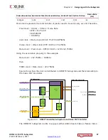
Pixel clock represents the total number of pixels need to be sent every second. Therefore,
Pixel clock = Htotal × Vtotal × Frame Rate
=2200 x 1125 x 60
=148,500,000
= 148.5Mhz
Link clock = (Data clock)/4=222.75/4=55.6875Mhz
Video clock = (Pixel clock)/PPC=148.5/2=74.25Mhz
Data clock = Pixel clock × BPC/8=148.5× 12/8=222.75Mhz
Using the associative property in this example,
Data clock = 222.75Mhz < 340Mhz
then
TMDS clock = Data clock = 222.75Mhz
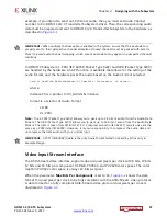
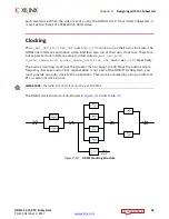
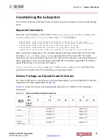
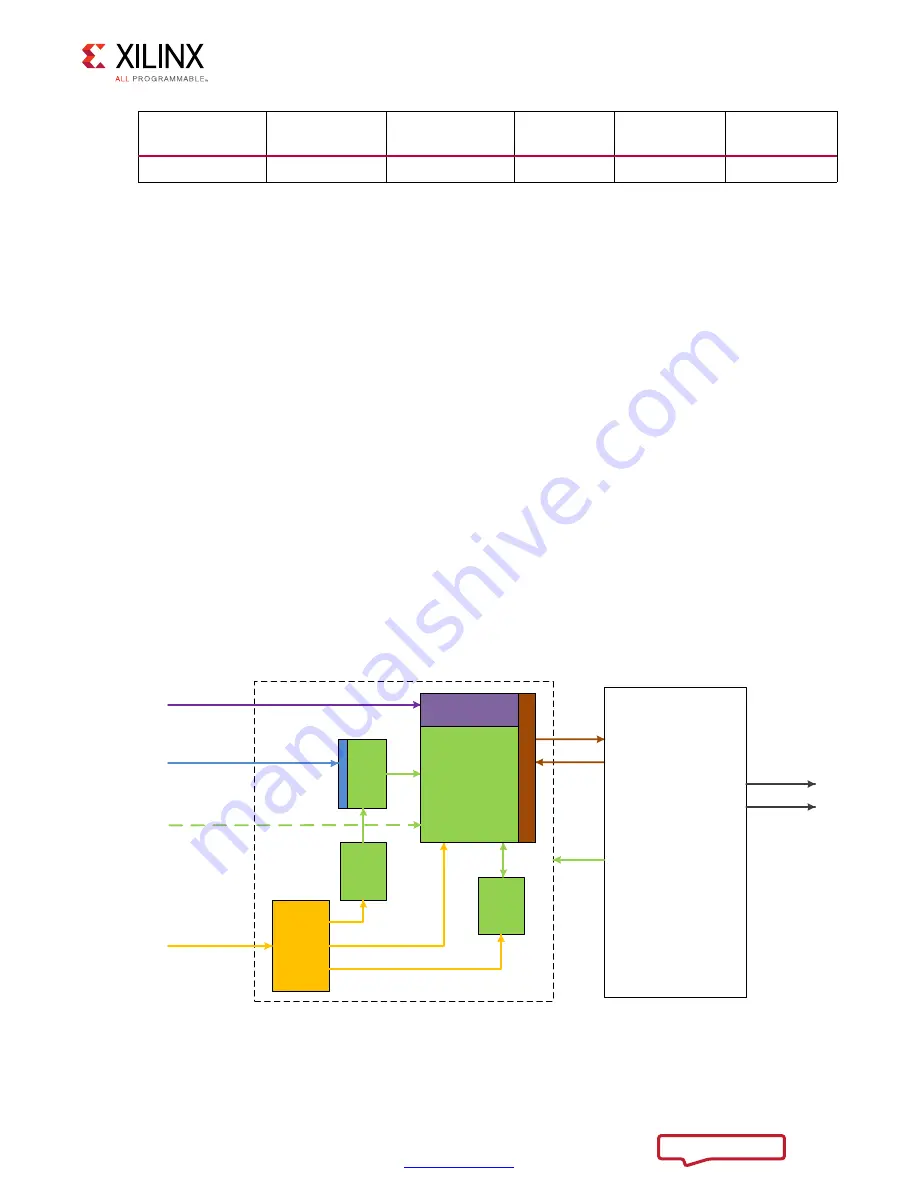
Figure shows how the clock is distributed in HDMI TX Subsystem and the relationship to
the Video PHY Controller.
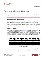
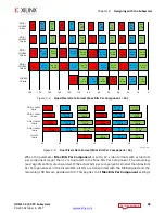
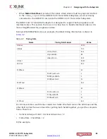
The HDMI TX Subsystem is able to support either AXI4-Stream Video or Native Video.
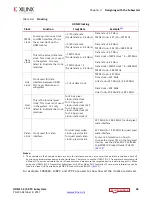
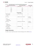
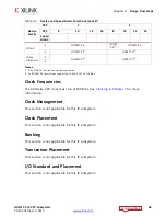
Video Resolution Horizontal Total Horizontal Active Vertical Total Vertical Active
Frame Rate
(Hz)
1080p60
2200
1920
1125
1080
60
X-Ref Target - Figure 3-11
Figure
3
‐
11:
HDMI Transmitter Subsystem and Video PHY Controller
AXI4-S
to
Video
Bridge
AXI4
Interconnect
Video
Timing
Controller
HDCP
(optional)
CPU interface
(AXI4-lite)
Video interface opt 1
(axis_video_aclk)
Audio interface
(axis_audio_aclk)
Link Data
Link Clock
TX Subsystem
HDMI TX
Core
Video interface opt 2
video_clk
tx_video_clk
txoutclk
vid_phy_tx_axi4s
Video Phy Controller
(video_clk)
tx_tmds_clk
phy_tx_out[2:0]
TMDS data
TMDS clock


