


EGCP-2 Engine Generator Control Package
Manual 26174
52
Woodward
76
77
485 (+)
RS-485 Termination
485 (-)
243
SW4-1
+5
Vdc
SW4-2
SW4-3
121.5
243
78
Shield
RS 422/485
Transceiver
81
82
RS-422 Termination
243
SW3-1
+5
Vdc
SW3-2
SW3-3
80
Shield
85
422 TxD (-)
422 RxD (+)
422 RxD (-)
84
422 TxD (+)
121.5
243
RS 422/485
Transceiver
83
VIS-108a
06-4-17
79
+5 Vdc
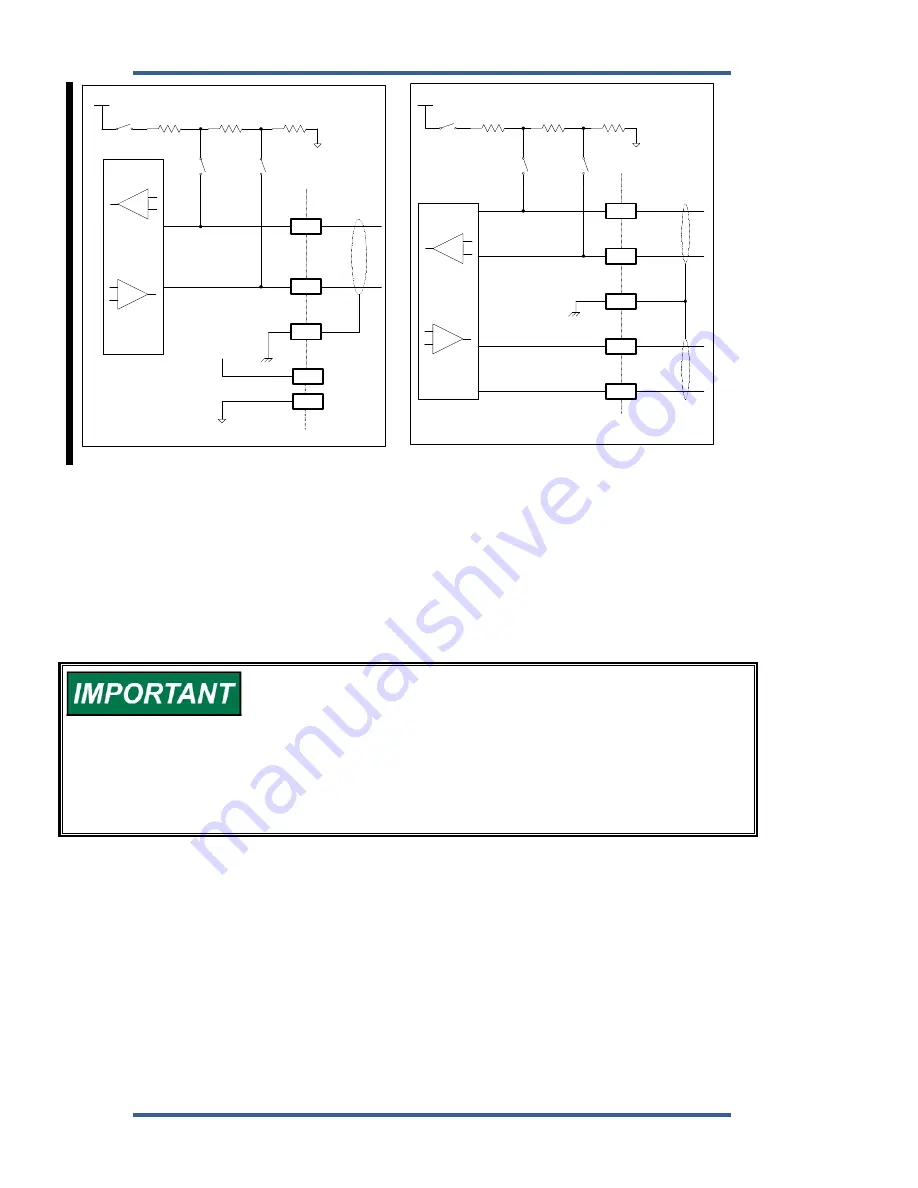
Figure 3-26. RS-485 and RS-422 Termination Diagrams
Inter-control Communications (RS-485 Network)
The EGCP-2 uses a proprietary communication structure to share information
between multiple EGCP-2 controls. This structure allows accurate load sharing,
status, and command messages to be exchanged between up to 8 controls. The
network uses RS-485 protocol over a standard twisted shielded pair to link the
EGCP-2 controls at terminals 76(+) and 77(–) with 78 the shield.
When EGCP-2 controls are installed with a distance of 1000 m or
greater between them, additional measures should be taken to
ensure solid communications. The wire gauge of the
communications link should be upgraded to 0.5–0.8 mm² (18–20
AWG) where larger sizes are used for longer distances. The larger
size wire will exhibit smaller voltage drop. If communications errors
are observed, terminal 80 can be connected from control to control
using 1.0 mm² (16 AWG) wiring. Making this connection will force all
communications transceivers to the same reference.
As shown in Figure 3-26, the EGCP-2 uses Switch 4 (4-1, 4-2, and 4-3) to
terminate the 485 network. Switches 4-1, 4-2, and 4-3 will be closed (pushed
down toward the PC board, see Figure 3-4) for proper 485 network terminations.
Proper network termination will ensure robust inter-control communications.