background image

Quick Start – 1

WheatNet-IP


/ Apr 2009

Before Getting Started

The purpose of this document is to aid in the quick setup of your new Wheatstone

WheatNet-IP


product. The WheatNet-IP


product comes with a setup wizard that will

walk you through the setup process. This wizard is designed to help you get the system
up and running quickly with little effort. If you have any issues during the setup process
please contact Wheatstone Technical Support for further assistance at (252) 638-7000.

The guide assumes that connectivity will take place by one of the following methods.

Isolated Network

It is recommended that connectivity of the WheatNet-IP


be made through an isolated

Gigabit Ethernet switch.

House Network

Careful planning should be done if the WheatNet-IP


system will integrate into your

house network. A separate VLAN or other isolation method must be deployed to contain
the multicast traffic. This guide assumes the network is equipped with a Gigabit network
switch or router capable of handling this type of configuration. Consult your IT
department for more information.

Snake Mode

This connection method assumes there will be two BLADEs connected back to back

via a crossover cable to provide a point-to-point audio link. See “Snake” in Chapter 2 of
this


manual.

Network Setup

BLADE ID

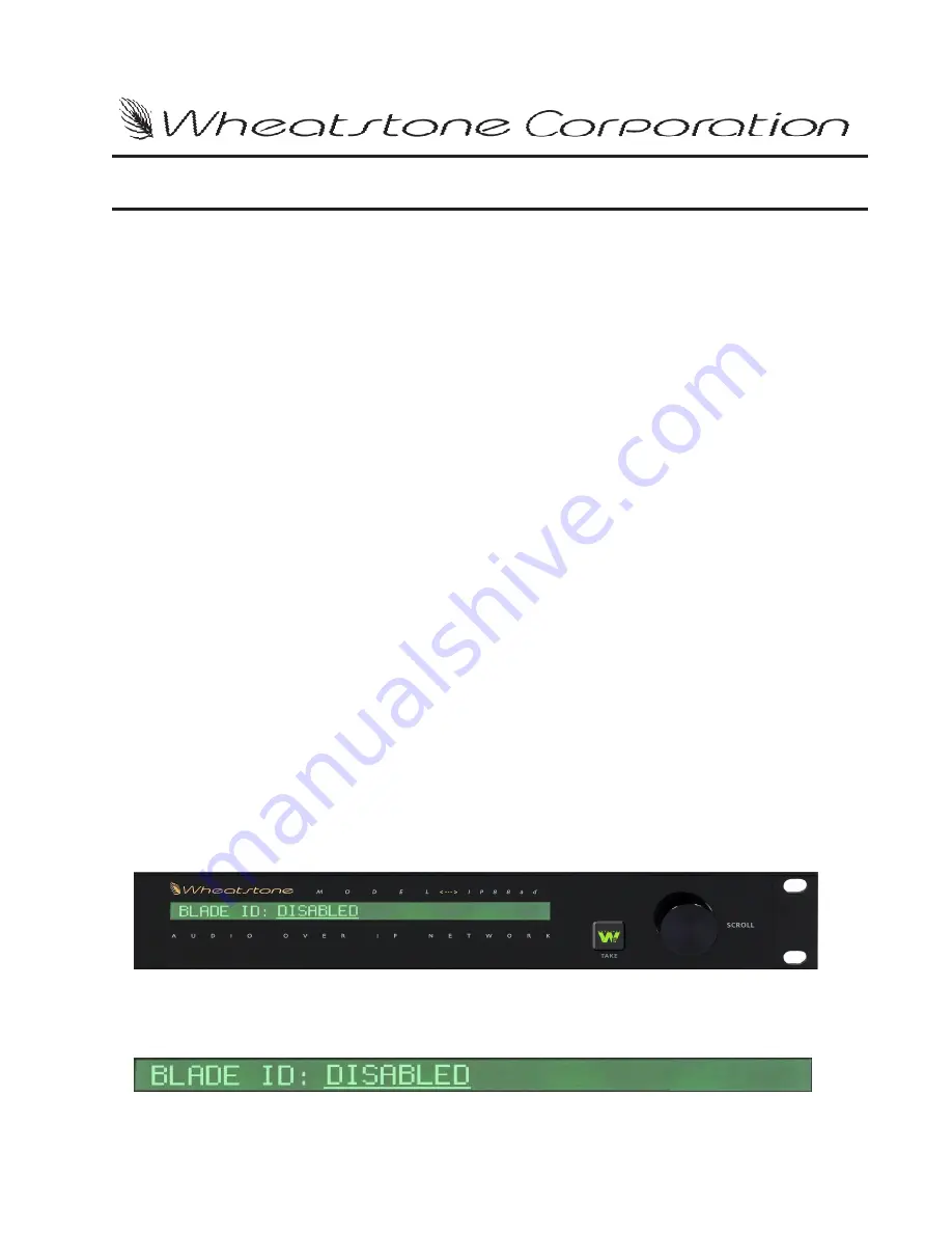
Once power is applied the BLADE Quick Setup wizard will start automatically,

assuming this is a first-time startup, and the front panel display should read as follows.

Rotate the encoder knob to the desired BLADE ID and press the TAKE button.

W h e a t N e t - I P   Q u i c k   S t a r t   S e t u p   G u i d e

WheatNet-IP


/ Jan 2010

Summary of Contents for WheatNet-IP Blade3s

Page 1: ...AUDIO OVER IP NETWORK 600 Industrial Drive New Bern N C 28562 tel 252 638 7000 fax 252 637 1285 email wheatstone com TECHNICAL MANUAL WheatNet IP ...

Page 2: ...TECHNICAL MANUAL Wheatstone Corporation April 2009 AUDIO OVER IP NETWORK WheatNet IP ...

Page 3: ...600 Industrial Drive New Bern North Carolina 28562 tel 252 638 7000 fax 252 637 1285 Wheatstone WheatNet IP Audio Over IP Network 3rd Edition Revised 2012 Wheatstone Corporation ...

Page 4: ...duct In a domestic environment this This is a Class A product In a domestic environment this This is a Class A product In a domestic environment this This is a Class A product In a domestic environment this product may cause radio interference in which case the product may cause radio interference in which case the product may cause radio interference in which case the product may cause radio inte...

Page 5: ...ided for your safety If the provided plug does not fit into your outlet consult an electrician for replacement of the obsolete outlet 10 Protectthepowercordfrombeingwalkedonorpinchedparticularlyatplugs convenience receptacles and the point where they exit from the apparatus 11 Only use attachments accessories specified by the manufacturer 12 Unplug this apparatus during lightning storms or when un...

Page 6: ...nie pour votre sécurité Si la fiche fournie ne rentre pas dans votre prise consultez un électricien pour le remplacement de la prise obsolète 10 Protéger le cordon d alimentation en évitant qu il ne soit piétiné ou écrasé notamment au niveau des fiches et le point de sortie de l appareil 11 N utiliser que les fixations et accessoires spécifiés par le fabricant 12 Débrancher cet appareil pendant le...

Page 7: ... Careful planning should be done if the WheatNet IP system will integrate into your house network A separate VLAN or other isolation method must be deployed to contain the multicast traffic This guide assumes the network is equipped with a Gigabit network switch or router capable of handling this type of configuration Consult your IT department for more information Snake Mode This connection metho...

Page 8: ...nd will up or down convert accordingly to the WheatNet IP sample rate Signal Setup Now that the Network Setup is complete the wizard will assist with creating audio signals if desired The WheatNet IPunit is equipped with signal templates to aid in quick setup These templates are standard signal setups that may be a good starting point depending on the application The WheatNet IP 88a 88d and 88ad h...

Page 9: ...up process the BLADE will attempt to join the network During this process a Connecting message will appear on the display Once the BLADE has successfully joined the network the front panel will display To access the Main Menu rotate the encoder and select the desired option by pressing Take Things To Look For In The Wizard If an online BLADE is detected with the same ID the wizard will display the...

Page 10: ...Series surface select YES from the dialog box The surface will now display the Options Tab See Figure 2 Here you will settheBLADEIDandIPaddressoftheEnginetowhichthesurfacewillconnect along with the Surface IP Address Subnet Mask and Gateway If Automatic mode is selected entertheBLADEIDoftheMixEngineBladetobeassociatedwiththesurface andremainingsettingsareconfiguredforyou Youcanmanuallyenterthisinf...

Page 11: ...ine BLADE 5 Surface IP Address 192 168 87 205 A Configuration Mode This is where you select the Configuration mode desired The choices are Automatic or Manual B Mix Engine ID This is where the ID of the Mix Engine Blade that will be associated with the surface is assigned One Mix Engine Blade supports a single surface C Blade Status This is the Blade connection status If properly configured and co...

Page 12: ... Once the surface has been rebooted navigate to the Options Tab and select Network Settings from the drop down menu If all information was entered properly the BLADE STATUS will display CON NECTED See Figure 4 The E Series surface has been successfully configured Figure 3 WheatNet IP June 2010 ...

Page 13: ...Quick Start 7 WheatNet IP Apr 2009 Figure 4 ...

Page 14: ...dded BLADE 1 12 Signal Configuration 1 12 Model MADI Multichannel Audio Digital BLADE 1 13 Model M4IP Microphone Processing BLADE 1 13a Model LIO 48 Multiple Port Logic I O BLADE 1 13b Network Switches 1 13b CAT 5e Wiring 1 14 AoIP Driver 1 14 Software Tools 1 14 Audio Devices 1 14 I O Connections 1 15 Model 88a 1 15 Inputs 1 15 Outputs 1 17 Models 88d 1 19 Inputs 1 19 Outputs 1 20 Model 88ad 1 21...

Page 15: ...igital BLADE Input Output Pinout Drawing 1 42 Microphone Processing BLADE M4IP Input Output Pinout Drawing 1 43 LIO 48 Multiple Port Logic I O BLADE Input Output Pinout Drawing 1 44 Stand Alone 2 2 Snake 2 6 Network 2 8 WheatNet IP Front Panel Menu Diagram 2 13 WheatNet IP Networks and What They Do 2 14 Overview 3 2 Gigabit Ethernet Technology 3 2 Choosing Ethernet Switches 3 2 Switch Feature Cons...

Page 16: ...n Detail 4 14 System Crosspoint Tab 4 14 System Crosspoint Details Menu 4 15 Choose View 4 15 Destinations Sort By 4 15 Sources Sort By 4 15 Show 4 16 Destination Details Menu 4 16 Choose View 4 16 Destinations Sort By 4 17 Show 4 17 Rename Signal 4 17 Modify Signal 4 18 Lock Signal 4 20 Source Details Menu 4 20 Choose View 4 20 Sources Sort By 4 21 Show 4 21 Rename Signal 4 21 Modify Signal 4 22 ...

Page 17: ...E Sources Tab 4 41 Source Signals 4 41 Free Resources 4 42 Meters 4 44 BLADE Destinations Tab 4 45 Destination Signals 4 45 Free Resources 4 46 Meters 4 48 BLADE Visibilities Tab 4 49 BLADE LIO Info Tab 4 51 BLADE Silence Detect Tab 4 52 Destination Signals 4 53 Settings 4 54 Status 4 55 Logic 4 55 Utility Mixer Tab 4 56 Network Info Tab 4 57 Version Manager Tab 4 58 Config Manager Tab 4 59 A Word...

Page 18: ...onfiguring the VLAN Interface A 16 5 IGMP Snooping Querier Configuration A 16 6 Configuring Gigabit Ports Connecting to WheatNet IP I O Blades and PC Drivers A 16 6 Configuring Gigabit Ports Connecting to WheatNet IP Control Surfaces GP Panels and XY Controllers A 16 7 Configuring Ports for Linking to Other Network Switches A 16 7 Checking and Saving the Switch Configuration A 16 8 HP Procurve 281...

Page 19: ...ERS GUI A 45 Adding Devices To The 3rd Party Tab A 45 Introduction To IP MTR64 Meters GUI A 46 IP MTR64 Meters GUI Overview A 46 IP MTR64 Meters GUI Features A 46 Installation A 47 Requirements A 47 Performing The Install A 47 Program Operation Getting Started A 49 License Key A 49 First Time Operation A 51 Network Setup A 51 Discovering The System Components A 53 Setting Up Meters A 55 Configurin...

Page 20: ...rst Time Operation A 68 If You Are Not Connected To A System A 68 Default Signal Warning A 68 License Warning A 68 License Key Entry A 69 Main Screen A 69 If You Are Connected To A System A 70 Set IP Address A 70 Day to Day Operation A 71 System A 71 Set IP Address A 71 Define Devices A 72 Signals A 73 Request Signals From Connected Blade A 73 Load Signals From File A 75 Save Signals To File A 76 ...

Page 21: ...Events A 86 Schedule A 87 Signals A 87 Help A 87 Event Log Menu A 88 Event Log Menu File A 88 Event Log Menu Edit A 88 WheatNet IP PC XY Software Configuration Guide A 90 Overview A 90 Installing The Software A 90 Network Considerations A 90 Logging In A 91 Menus A 91 Setting Blade IP Address A 91 Using Source Destination Windows A 92 Logging Out A 92 Visibilities A 92 Hot Button Programming A 93 ...

Page 22: ...ine DSP 1 11 Model Aura8ip Vorsis Embedded BLADE 1 12 Signal Configuration 1 12 Model MADI Multichannel Audio Digital BLADE 1 13 Model M4IP Microphone Processing BLADE 1 13a Model LIO 48 Multiple Port Logic I O BLADE 1 13b Network Switches 1 13b CAT 5e Wiring 1 14 AoIP Driver 1 14 Software Tools 1 14 Audio Devices 1 14 I O Connections 1 15 Model 88a 1 15 Inputs 1 15 Outputs 1 17 Models 88d 1 19 In...

Page 23: ...g 1 35 Digital 88d Input Output Pinout Drawing 1 36 Analog Digital 88ad Input Output Pinout Drawing 1 37 Analog MIC 88m Input Output Pinout Drawing 1 38 Console Blade 88cb 88cbe Input Output Pinout Drawing 1 39 Engine e Input Output Pinout Drawing 1 40 Vorsis Embedded BLADE Aura8ip Input Output Pinout Drawing 1 41 Multichannel Audio Digital BLADE Input Output Pinout Drawing 1 42 Microphone Process...

Page 24: ...in place in the form of your LAN and its CAT 5e cables You ll only need to wire your source and destina tion devices to BLADEs to complete your system Best of all the dozens of audio cables and hundreds of logic connections you used to need to connect up each audio console have been replaced with a single CAT 5e cable to the control surface What could be easier A word about latency a finite and no...

Page 25: ... run hotter and should be installed with spaces in between to avoid detrimental heat build up WARNING Under no circumstances should the WheatNet IP unit be opened The unit contains high voltage circuits that are hazardous and potentially harmful The unit has no user serviceable parts inside If you have a problem the unit must be returned to Wheatstone Corporation for repair Installation Tips Place...

Page 26: ...using sensitive modern electronic devices that use an internal computer Use of a UPS uninterruptible power supply is a good idea and will protect the WheatNet IPfrom short duration power interruptions which may cause it to reboot During boot up audio is interrupted for approximately 40 seconds A Word About Nomenclature Throughout this manual references are made to BLADEs sources des tinations and ...

Page 27: ...e 5 GUI Shorthand for Graphical User Interface A method of providing for user interaction with the system using a special computer program that displays information in the form of images and text on the computer screen and accepts user input via typing and mouse clicking within the computer program The WheatNet IP Navigator is a computer program that provides a GUI 6 Web Server Aspecial computer p...

Page 28: ...F O R M A T I O N page 1 7 WheatNet IP Aug 2011 WheatNet IP System Description Let s take a look at the parts of the WheatNet IP system in more detail First there are the BLADEs themselves of which there are five flavors ...

Page 29: ...There are two RJ 45 jacks for Ethernet One is for 1 Gigabit Ethernet connect this one to your network The 100 Megabit Ethernet port is not used do not con nect anything to this port Consult the wiring diagram at the page 1 35 for detailed information The unit has a standard IEC power connector The BLADEs have an internal power supply that will accept 100 240 volts 50 60 hertz AC power Model 88d Di...

Page 30: ... your preferred connector type for audio inputs These can be set up as eight stereo 16 mono or any combination up to a maximum of 16 discrete channels The first DB 25 and the first four RJ 45 jacks are set up as analog inputs The second DB 25 and the last four RJ 45 jacks are set up as AES digital inputs It also has two DB 25 and eight RJ 45 connectors again use your preferred connector for audio ...

Page 31: ...power can be applied independently to each of the individual inputs It also has one DB 25 and eight RJ 45 connectors the DB and RJ connections are in parallel so you can choose your preferred connector type for audio outputs Only the first four RJ 45 ports are used These can be set up as four stereo eight mono or any com bination up to a maximum of eight discrete channels These are setup as analog...

Page 32: ... Megabit Ethernet port is not used do not connect anything to this port Consult the wiring diagram on page 1 39 for detailed information The unit has a standard IEC power connector The BLADEs have an internal power supply that will accept 100 240 volts 50 60 hertz AC power Model e Mix Engine DSP WheatNet IP e is a special device that contains the mix engine and signal processing needed for a contr...

Page 33: ...rs to provide 12 logic ports which can be individually designated during set up as inputs or outputs These ports are where you wire the various external switches indicators and control functions you need in your facility There are two RJ 45 jacks for Ethernet One is for 1 Gigabit Ethernet connect this one to your network The 100 Megabit Ethernet port is not used do not connect anything to this por...

Page 34: ...l Audio Digital Interface BLADE The MADI BLADE is an access point on the WheatNet IP Intelligent Network con verting a 64 channel MADI input to data streams on the network and converting data streams to 64 channel MADI outputs The MADI BLADE bridges the gap between any MADI capable audio gear or network and the WheatNet IP Intelligent Network With the MADI BLADE users can add on to their existing ...

Page 35: ...quality microphone processors and both digital and analog outputs The Wheatstone M4IP hosts four discrete very high quality microphone processors The Vorsis Embedded processing features of the M4IP the processing capabilities of the M4IP and how to control it with the included Windows based GUI application are described in the M4IP Microphone Processing BLADE technical manual This unit has four XL...

Page 36: ...he bottom one provides a 1 Gigabit connection to the WheatNet IP network At the far right of the rear panel is a standard IFC power connector The LIO 48 has an internal power supply that will accept 100 240 Volts 50 60 Hertz AC power Consult the wiring diagram on page 1 44 for detailed information Network Switches The next component of the WheatNet IP system is your network switch es These are sta...

Page 37: ...t you wish to get audio to from On a modern PC the driver will allow up to eight different audio streams play ing back simultaneously while accepting eight different audio input streams That s a lot of audio representing over half of the total bandwidth available on the standard 100 Mbit Ethernet NIC card installed in most PCs Please note that any PC can use the WheatNet IP AoIP driver it doesn t ...

Page 38: ...d from analog line level inputs via two DB 25 or eight RJ 45 connectors The line level analog audio inputs are 4dBu balanced The analog line inputs exhibit a bridging impedance and can handle signals up to 20dBu Analog 1 4 DB 25 Pin 24 HI Pin 12 LO Line 1 Lt In Pin 25 SH Pin 10 HI Pin 23 LO Line 1 Rt In Pin 11 SH Pin 21 HI Pin 9 LO Line 2 Lt In Pin 22 SH Pin 7 HI Pin 20 LO Line 2 Rt In Pin 8 SH Pi...

Page 39: ...RT In Pin 2 SH Analog 1 8 RJ 45 RJ 45 1 Pin 1 HI RJ 45 1 Pin 2 LO RJ 45 1 Pin 3 HI RJ 45 1 Pin 6 LO RJ 45 2 Pin 1 HI RJ 45 2 Pin 2 LO RJ 45 2 Pin 3 HI RJ 45 2 Pin 6 LO RJ 45 3 Pin 1 HI RJ 45 3 Pin 2 LO RJ 45 3 Pin 3 HI RJ 45 3 Pin 6 LO RJ 45 4 Pin 1 HI RJ 45 4 Pin 2 LO RJ 45 4 Pin 3 HI RJ 45 4 Pin 6 LO RJ 45 5 Pin 1 HI RJ 45 5 Pin 2 LO RJ 45 5 Pin 3 HI RJ 45 5 Pin 6 LO RJ 45 6 Pin 1 HI RJ 45 6 Pin...

Page 40: ...in 25 SH Pin 10 HI Pin 23 LO Line 1 Rt Out Pin 11 SH Pin 21 HI Pin 9 LO Line 2 Lt Out Pin 22 SH Pin 7 HI Pin 20 LO Line 2 Rt Out Pin 8 SH Pin 18 HI Pin 6 LO Line 3 Lt Out Pin 19 SH Pin 4 HI Pin 17 LO Line 3 Rt Out Pin 5 SH Pin 15 HI Pin 3 LO Line 4 Lt Out Pin 16 SH Pin 1 HI Pin 14 LO Line 4 Rt Out Pin 2 SH Analog 5 8 DB 25 Pin 24 HI Pin 12 LO Line 5 Lt Out Pin 25 SH Pin 10 HI Pin 23 LO Line 5 Rt O...

Page 41: ...5 3 Pin 1 HI RJ 45 3 Pin 2 LO RJ 45 3 Pin 3 HI RJ 45 3 Pin 6 LO RJ 45 4 Pin 1 HI RJ 45 4 Pin 2 LO RJ 45 4 Pin 3 HI RJ 45 4 Pin 6 LO RJ 45 5 Pin 1 HI RJ 45 5 Pin 2 LO RJ 45 5 Pin 3 HI RJ 45 5 Pin 6 LO RJ 45 6 Pin 1 HI RJ 45 6 Pin 2 LO RJ 45 6 Pin 3 HI RJ 45 6 Pin 6 LO RJ 45 7 Pin 1 HI RJ 45 7 Pin 2 LO RJ 45 7 Pin 3 HI RJ 45 7 Pin 6 LO RJ 45 8 Pin 1 HI RJ 45 8 Pin 2 LO RJ 45 8 Pin 3 HI RJ 45 8 Pin 6...

Page 42: ...l reference and a digital input 8 from a different BLADE to be a secondary external reference Please note that the sample rate of a digital input 8 should be the same either 44 1kHz or 48kHz as the system s chosen sample rate AES sources are by design stereo if the BLADE is not set to be stereo the ap propriate Left or Right signal within the AES stream will be applied to the signal path Digital 1...

Page 43: ...in 1 HI RJ 45 7 Pin 2 LO RJ 45 8 Pin 1 HI RJ 45 8 Pin 2 LO Outputs Digital 1 4 DB 25 Pin 24 HI Pin 12 LO AES 1 Out Pin 25 SH Pin 21 HI Pin 9 LO AES 2 Out Pin 22 SH Pin 18 HI Pin 6 LO AES 3 Out Pin 19 SH Pin 15 HI Pin 3 LO AES 4 Out Pin 16 SH Digital 5 8 DB 25 Pin 24 HI Pin 12 LO AES 5 Out Pin 25 SH Pin 21 HI Pin 9 LO AES 6 Out Pin 22 SH Pin 18 HI Pin 6 LO AES 7 Out Pin 19 SH Pin 15 HI Pin 3 LO AES...

Page 44: ...e rate converted to the system s chosen sample rate of 44 1kHz or 48kHz which is set via the WheatNet IP Navigator GUI The GUI also allows you to select input 8 of the digital BLADE or of any BLADE that has a digital input as input 8 to be a primary external reference and a digital input 8 from a different BLADE to be a secondary external reference Please note that the sample rate of a digital inp...

Page 45: ...Pin 12 LO AES 5 In Pin 25 SH Pin 21 HI Pin 9 LO AES 6 In Pin 22 SH Pin 18 HI Pin 6 LO AES 7 In Pin 19 SH Pin 15 HI Pin 3 LO AES 8 In Pin 16 SH Analog 1 4 RJ 45 RJ 45 1 Pin 1 HI RJ 45 1 Pin 2 LO RJ 45 1 Pin 3 HI RJ 45 1 Pin 6 LO RJ 45 2 Pin 1 HI RJ 45 2 Pin 2 LO RJ 45 2 Pin 3 HI RJ 45 2 Pin 6 LO RJ 45 3 Pin 1 HI RJ 45 3 Pin 2 LO RJ 45 3 Pin 3 HI RJ 45 3 Pin 6 LO RJ 45 4 Pin 1 HI RJ 45 4 Pin 2 LO RJ...

Page 46: ...23 LO Line 1 Rt Out Pin 11 SH Pin 21 HI Pin 9 LO Line 2 Lt Out Pin 22 SH Pin 7 HI Pin 20 LO Line 2 Rt Out Pin 8 SH Pin 18 HI Pin 6 LO Line 3 Lt Out Pin 19 SH Pin 4 HI Pin 17 LO Line 3 Rt Out Pin 5 SH Pin 15 HI Pin 3 LO Line 4 Lt Out Pin 16 SH Pin 1 HI Pin 14 LO Line 4 Rt Out Pin 2 SH Digital 5 8 DB 25 Pin 24 HI Pin 12 LO AES 5 Out Pin 25 SH Pin 21 HI Pin 9 LO AES 6 Out Pin 22 SH Pin 18 HI Pin 6 LO...

Page 47: ...J 45 8 Pin 1 HI RJ 45 8 Pin 2 LO Model 88m Inputs The WheatNet IP 88m analog mono mic level input 50dBu nominal is fed from the female XLR connector to the internal microphone preamplifier The mic preamp has digitally controlled gain up to a maximum of 70 dB and displays remarkably high performance and accuracy Phantom power is available Analog 1 8 XLR XLR 1 Pin 1 SH XLR 1 Pin 2 HI Mic 1 In XLR 1 ...

Page 48: ...level 4dBu balanced or mono mic level 50dBu on the DB 25 connector or on the four RJ 45 1 through 4 connectors Analog 1 4 DB 25 Pin 24 HI Pin 12 LO Line 1 Lt Out Pin 25 SH Pin 10 HI Pin 23 LO Line 1 Rt Out Pin 11 SH Pin 21 HI Pin 9 LO Line 2 Lt Out Pin 22 SH Pin 7 HI Pin 20 LO Line 2 Rt Out Pin 8 SH Pin 18 HI Pin 6 LO Line 3 Lt Out Pin 19 SH Pin 4 HI Pin 17 LO Line 3 Rt Out Pin 5 SH Pin 15 HI Pin ...

Page 49: ...level analog audio inputs are 4dBu balanced The analog line inputs exhibit a bridging impedance and can handle signals up to 20dBu To handle digital line level sources there are also four RJ 45 connectors The digital inputs of the WheatNet IP 88cb and 88cbe inputs 5 8 will accommo date digital inputs having a wide range of sample rates These inputs will be sample rate converted to the system s cho...

Page 50: ...e WheatNet IP88cb and 88cbe provide four stereo analog outputs on RJ 45 conec tors four digitalAES formatted outputs on RJ 45 connectors cue and headphone outputs on RJ 45 connector and on 1 4 jacks and control room and studio monitor outputs on XLR male connectors MIC OUTS RJ 45 RJ 45 Pin 1 HI RJ 45 Pin 2 LO RJ 45 Pin 3 HI RJ 45 Pin 6 LO CUE HDPN OUT RJ 45 RJ 45 Pin 1 HI RJ 45 Pin 2 LO RJ 45 Pin ...

Page 51: ...in 1 HI RJ 45 A Pin 2 LO RJ 45 A Pin 3 HI RJ 45 A Pin 6 LO RJ 45 B Pin 1 HI RJ 45 B Pin 2 LO RJ 45 B Pin 3 HI RJ 45 B Pin 6 LO RJ 45 C Pin 1 HI RJ 45 C Pin 2 LO RJ 45 C Pin 3 HI RJ 45 C Pin 6 LO RJ 45 D Pin 1 HI RJ 45 D Pin 2 LO RJ 45 D Pin 3 HI RJ 45 D Pin 6 LO PGM OUT DIGITAL RJ 45 RJ 45 A Pin 1 HI RJ 45 A Pin 2 LO RJ 45 B Pin 1 HI RJ 45 B Pin 2 LO RJ 45 C Pin 1 HI RJ 45 C Pin 2 LO RJ 45 D Pin 1...

Page 52: ...sample rate of a digital input 8 should be the same either 44 1kHz or 48kHz as the system s chosen sample rate If you are using the Aura8ip in a stand alone application one involving no other BLADEs and if the outputs from Aura8ip must be synchronized to downstream digital equipment you must use input 8 for your external reference even if you are not using all 8 inputs AES sources are by design st...

Page 53: ...HI RJ 45 2 Pin 6 LO RJ 45 3 Pin 1 HI RJ 45 3 Pin 2 LO RJ 45 3 Pin 3 HI RJ 45 3 Pin 6 LO RJ 45 4 Pin 1 HI RJ 45 4 Pin 2 LO RJ 45 4 Pin 3 HI RJ 45 4 Pin 6 LO Digital 5 8 RJ 45 RJ 45 5 Pin 1 HI RJ 45 5 Pin 2 LO RJ 45 6 Pin 1 HI RJ 45 6 Pin 2 LO RJ 45 7 Pin 1 HI RJ 45 7 Pin 2 LO RJ 45 8 Pin 1 HI RJ 45 8 Pin 2 LO Outputs Analog 1 4 DB 25 Pin 24 HI Pin 12 LO Line 1 Lt Out Pin 25 SH Pin 10 HI Pin 23 LO L...

Page 54: ... 12 LO AES 5 Out Pin 25 SH Pin 21 HI Pin 9 LO AES 6 Out Pin 22 SH Pin 18 HI Pin 6 LO AES 7 Out Pin 19 SH Pin 15 HI Pin 3 LO AES 8 Out Pin 16 SH Analog 1 4 RJ 45 RJ 45 1 Pin 1 HI RJ 45 1 Pin 2 LO RJ 45 1 Pin 3 HI RJ 45 1 Pin 6 LO RJ 45 2 Pin 1 HI RJ 45 2 Pin 2 LO RJ 45 2 Pin 3 HI RJ 45 2 Pin 6 LO RJ 45 3 Pin 1 HI RJ 45 3 Pin 2 LO RJ 45 3 Pin 3 HI RJ 45 3 Pin 6 LO RJ 45 4 Pin 1 HI RJ 45 4 Pin 2 LO R...

Page 55: ...The MADI BLADE supports an optional fiber connection to the Bridge Router The MADI BLADE uses an SFPmodule interface with integral LC connectors Note that the QOT 2001 rear panel on the Bridge router uses SC connectors so to connect to a Bridge MADI card a patch cable fitted with LC connectors on one end and SC connectors on the other end is required Optical Transceiver Optical Transceivers conver...

Page 56: ...ive hence dual zip cables are recommended Optical fiber cables are manufactured with a variety of jacket materials which directly affect cable cost including Thermoplastic Elastomer TPE Kynar and Teflon FEP Physical properties of the jacket material determine a cable s resistance to abrasions flame retardancy etc Check local codes to be sure the cable you plan on using is compliant in your applica...

Page 57: ...n 22 SH Pin 7 HI Pin 20 LO Line 2 Rt Out Pin 8 SH Pin 18 HI Pin 6 LO Line 3 Lt Out Pin 19 SH Pin 4 HI Pin 17 LO Line 3 Rt Out Pin 5 SH Pin 15 HI Pin 3 LO Line 4 Lt Out Pin 16 SH Pin 1 HI Pin 14 LO Line 4 Rt Out Pin 2 SH Analog 1 4 RJ 45 RJ 45 1 Pin 1 HI RJ 45 1 Pin 2 LO RJ 45 1 Pin 3 HI RJ 45 1 Pin 6 LO RJ 45 2 Pin 1 HI RJ 45 2 Pin 2 LO RJ 45 2 Pin 3 HI RJ 45 2 Pin 6 LO RJ 45 3 Pin 1 HI RJ 45 3 Pi...

Page 58: ...45 Pin 6 Logic 5 In Out RJ 45 Pin 7 Logic 6 In Out RJ 45 Pin 8 5V Digital LOGIC I O 7 12 RJ 45 RJ 45 Pin 1 Digital Ground RJ 45 Pin 2 Logic 7 In Out RJ 45 Pin 3 Logic 8 In Out RJ 45 Pin 4 Logic 9 In Out RJ 45 Pin 5 Logic 10 In Out RJ 45 Pin 6 Logic 11 In Out RJ 45 Pin 7 Logic 12 In Out RJ 45 Pin 8 5V Digital LIO 48 Logic Ports The rear panel has eight RJ 45 connectors that have the connections for...

Page 59: ... Out Pin 9 Logic 9 In Out Pin 10 Logic 10 In Out Pin 11 Logic 11 In Out Pin 12 Logic 12 In Out Pin 13 Logic 13 In Out Pin 14 Logic 14 In Out Pin 15 Logic 15 In Out Pin 16 Logic 16 In Out Pin 17 Logic 17 In Out Pin 18 Logic 18 In Out Pin 19 Logic 19 In Out Pin 20 Logic 20 In Out Pin 21 Logic 21 In Out Pin 22 Logic 22 In Out Pin 23 Logic 23 In Out Pin 24 Logic 24 In Out Pin 25 Digital Ground The 25 ...

Page 60: ... 8 5VDC CONTROL START GND OPTO ISOLATED EXTERNAL DEVICE V START X OR LOGIC OUTPUT DGND Output Port Specs Sink 50mA nom 100mA max X 1 LOGIC INPUT INPUT PIN EXTERNAL CLOSURE DGND BLADE LIO PORT Input Port Specs Internally current limited No pull up required B U U W RJ 45 LIO 1 CT7 COLOR CODES T568A T568B WHT GRN WHT ORG GND C1 C2 C3 C4 C5 C6 C7 C8 GRN ORG LIO_RJ_1 WHT ORG WHT GRN LIO_RJ_2 BL LU LIO_...

Page 61: ... SH LINE 3 LT OUT HI LINE 3 RT OUT LO LINE 4 LT OUT SH LINE 4 LT OUT HI LINE 4 RT OUT LO AUDIO GROUND LINE 1 LT OUT LO LINE 1 RT OUT SH LINE 1 RT OUT HI LINE 2 LT OUT LO LINE 2 RT OUT SH LINE 2 RT OUT HI LINE 3 LT OUT LO LINE 3 RT OUT SH LINE 3 RT OUT HI LINE 4 LT OUT LO LINE 4 RT OUT SH LINE 4 RT OUT HI 5 4 3 2 1 17 16 15 14 8 7 6 20 19 18 10 9 23 22 21 13 12 11 25 24 LINE 1 LT OUT SH LINE 2 LT O...

Page 62: ...SH AES 3 OUT HI N C AES 4 OUT SH AES 4 OUT HI N C AUDIO GROUND AES 1 OUT LO N C N C AES 2 OUT LO N C N C AES 3 OUT LO N C N C AES 4 OUT LO N C N C 5 4 3 2 1 17 16 15 14 8 7 6 20 19 18 10 9 23 22 21 13 12 11 25 24 AES 1 OUT SH AES 2 OUT SH 1 4 DB 25 AES 5 OUT HI N C AES 6 OUT HI N C AES 7 OUT SH AES 7 OUT HI N C AES 8 OUT SH AES 8 OUT HI N C AUDIO GROU ND AES 5 OUT LO N C N C AES 6 OUT LO N C N C A...

Page 63: ...HI 5 4 3 2 1 17 16 15 14 8 7 6 20 19 18 10 9 23 22 21 13 12 11 25 24 LINE 1 LT IN SH LINE 2 LT IN SH 1 4 DB 25 1 2 3 4 5 6 7 8 RJ 45 1 LINE 1 LT IN HI LINE 1 LT IN LO LINE 1 RT IN HI LINE 1 RT IN LO 1 2 3 4 5 6 7 8 RJ 45 2 1 2 3 4 5 6 7 8 RJ 45 3 1 2 3 4 5 6 7 8 RJ 45 4 1 2 3 4 5 6 7 8 RJ 45 5 1 2 3 4 5 6 7 8 RJ 45 6 1 2 3 4 5 6 7 8 RJ 45 7 1 2 3 4 5 6 7 8 RJ 45 8 LINE 2 LT IN HI LINE 2 LT IN LO L...

Page 64: ... RT OUT HI LINE 3 LT OUT LO LINE 3 RT OUT SH LINE 3 RT OUT HI LINE 4 LT OUT LO LINE 4 RT OUT SH LINE 4 RT OUT HI 5 4 3 2 1 17 16 15 14 8 7 6 20 19 18 10 9 23 22 21 13 12 11 25 24 LINE 1 LT OUT SH LINE 2 LT OUT SH ANALOG OUTPUTS 1 4 DB 25 1 2 3 4 5 6 7 8 RJ 45 1 LINE 1 LT OUT HI LINE 1 LT OUT LO LINE 1 RT OUT HI LINE 1 RT OUT LO 1 2 3 4 5 6 7 8 RJ 45 2 1 2 3 4 5 6 7 8 RJ 45 3 1 2 3 4 5 6 7 8 RJ 45 ...

Page 65: ... 7 IN LO AES 8 IN HI AES 8 IN LO 2 3 1 XLR M 1 PIN 1 ST LT OUT SH PIN 2 ST LT OUT HI PIN 3 ST LT OUT LO 2 3 1 XLR M 1 PIN 1 CR LT OUT SH PIN 2 CR LT OUT HI PIN 3 CR LT OUT LO 2 3 1 XLR M 2 PIN 1 ST RT OUT SH PIN 2 ST RT OUT HI PIN 3 ST RT OUT LO 2 3 1 XLR M 2 PIN 1 CR RT OUT SH PIN 2 CR RT OUT HI PIN 3 CR RT OUT LO STUDIO OUT CR OUT 1 2 3 4 5 6 7 8 RJ 45 A PGM A LT OUT HI PGM A LT OUT LO PGM A RT ...

Page 66: ...TRD1 TRD2 TRD2 TRD3 TRD3 1G RJ 45 ETHERNET NOT USED 1 2 3 4 5 6 7 8 1 6 RJ 45 1 2 3 4 5 6 7 8 7 12 RJ 45 DIGITAL GROUND LOGIC 1 IN OUT LOGIC 2 IN OUT LOGIC 3 IN OUT LOGIC 4 IN OUT LOGIC 5 IN OUT LOGIC 6 IN OUT 5V DIGITAL DIGITAL GROUND LOGIC 7 IN OUT LOGIC 8 IN OUT LOGIC 9 IN OUT LOGIC 10 IN OUT LOGIC 11 IN OUT LOGIC 12 IN OUT 5V DIGITAL LOGIC I O ...

Page 67: ...T IN HI 5 4 3 2 1 17 16 15 14 8 7 6 20 19 18 10 9 23 22 21 13 12 11 25 24 LINE 1 LT IN SH LINE 2 LT IN SH 1 4 DB 25 1 2 3 4 5 6 7 8 RJ 45 1 LINE 1 LT IN HI LINE 1 LT IN LO LINE 1 RT IN HI LINE 1 RT IN LO 1 2 3 4 5 6 7 8 RJ 45 2 1 2 3 4 5 6 7 8 RJ 45 3 1 2 3 4 5 6 7 8 RJ 45 4 1 2 3 4 5 6 7 8 RJ 45 5 1 2 3 4 5 6 7 8 RJ 45 6 1 2 3 4 5 6 7 8 RJ 45 7 1 2 3 4 5 6 7 8 RJ 45 8 LINE 2 LT IN HI LINE 2 LT IN...

Page 68: ...D 1 2 3 4 5 6 7 8 1 6 RJ 45 1 2 3 4 5 6 7 8 7 12 RJ 45 DIGITAL GROUND LOGIC 1 IN OUT LOGIC 2 IN OUT LOGIC 3 IN OUT LOGIC 4 IN OUT LOGIC 5 IN OUT LOGIC 6 IN OUT 5V DIGITAL DIGITAL GROUND LOGIC 7 IN OUT LOGIC 8 IN OUT LOGIC 9 IN OUT LOGIC 10 IN OUT LOGIC 11 IN OUT LOGIC 12 IN OUT 5V DIGITAL LOGIC I O INPUT BNC PIN 1 INPUT HI PIN 2 INPUT SH OUTPUT BNC PIN 1 OUTPUT HI PIN 2 OUTPUT SH FIBER LC CONNECTO...

Page 69: ...1 IN OUT LOGIC 2 IN OUT LOGIC 3 IN OUT LOGIC 4 IN OUT LOGIC 5 IN OUT LOGIC 6 IN OUT 5V DIGITAL DIGITAL GROUND LOGIC 7 IN OUT LOGIC 8 IN OUT LOGIC 9 IN OUT LOGIC 10 IN OUT LOGIC 11 IN OUT LOGIC 12 IN OUT 5V DIGITAL LOGIC I O WheatNet IP May 2013 1 2 3 4 5 6 7 8 RJ 45 1 LINE 1 LT OUT HI LINE 1 LT OUT LO LINE 1 RT OUT HI LINE 1 RT OUT LO 1 2 3 4 5 6 7 8 RJ 45 2 1 2 3 4 5 6 7 8 RJ 45 3 1 2 3 4 5 6 7 8...

Page 70: ...IN OUT 5 4 3 2 1 17 16 15 14 8 7 6 20 19 18 10 9 23 22 21 13 12 11 25 24 DIGITAL GROUND LOGIC 46 IN OUT 2 1 7 6 5 4 3 9 8 5V LOGIC 5 DIGITAL GROUND 5V LOGIC 8 5V LOGIC 6 5V LOGIC 4 5V LOGIC 3 5V LOGIC 2 5V LOGIC 1 5V LOGIC 7 5VDC DB 9 1 2 3 4 5 6 7 8 A RJ 45 1 2 3 4 5 6 7 8 E RJ 45 AUDIO GROUND LOGIC 1 IN OUT LOGIC 2 IN OUT LOGIC 3 IN OUT LOGIC 4 IN OUT LOGIC 5 IN OUT LOGIC 6 IN OUT 5V DIGITAL AUD...

Page 71: ... O N A L M O D E S page 2 1 WheatNet IP Apr 2009 WheatNet IP System Operational Modes Chapter Contents Stand Alone 2 2 Snake 2 6 Network 2 8 WheatNet IP Front Panel Menu Diagram 2 13 WheatNet IP Networks and What They Do 2 14 WheatNet IP June 2010 ...

Page 72: ...ith analog and digital inputs and outputs to give you maximum flexibility This stand alone system can be added to a network as your needs change and expansion is required As a stand alone router no network connection or Ethernet switch is required If you choose to connect the BLADE to a network you can do things like set levels remotely meter and monitor all inputs and outputs mix channels use sil...

Page 73: ...nals are automatically defined Choose CUSTOM only if you need a combination of mono and stereo signals within the BLADE You ll have to do more work and define the signals yourself For WheatNet IP 88m there are two signal templates available Choose from MONO_MIC which creates eight microphone inputs and eight mono outputs or STEREO_MIC which creates eight microphone inputs and four stereo outputs F...

Page 74: ...tination 1 Pressing the front panel switch will change the source section of the display to show underlines flashing under the source name indicating that the source can now be changed Scroll the knob until the desired source is shown and press the switch The crosspoint connection will be made and the display will change to indicate the destination source connection Turning the knob again will cha...

Page 75: ...ny other one You can use the front panel encoder to set the front panel meter mode for the BLADE There are 16 LED bargraph meters on the front panel These can show either the input signal levels for each source or the output signal levels for each destination To choose scroll through the front panel menus until you find ME TERS and select it with the switch The front panel display will change to s...

Page 76: ...nnect the Gigabit Ethernet port of the first BLADE directly to the Gigabit Ethernet port of the second BLADE No Ethernet switch is required Power up both BLADEs and at the BLADE ID DISABLED start up screen scroll the encoder knob through the various IDs and select SNAKE A for the first BLADE Hint if you scroll the knob backwards counterclockwise you will get to the SNAKE A selection much quicker R...

Page 77: ... 1 is connected to destination 1 in BLADE 2 source 2 from BLADE 1 is connected to destination 2 in BLADE 2 etc Likewise source 1 from BLADE 2 is connected to destination 1 in BLADE 1 and so forth for a total of 32 channels of audio 16 one direction and 16 more the reverse direction over a single CAT 5e cable which by the way is much less expensive and easier to manage than an old 32 channel audio ...

Page 78: ... of multiple BLADEs control surfaces and other devices In this mode every BLADE is a member of the networkandisidentifiedwithitsnameandID TheBLADEIDiscrucialtopropersystem operation each member of the network must have a unique ID number This number is a simple decimal number from ID 1 to ID 99 that is chosen by the user when the BLADE is first started up ...

Page 79: ...ion the bandwidth and traffic patterns on the network must be carefully controlled For these reasons Wheatstone strongly recommends that the WheatNet IP system and its various components be isolated either physically or virtually on its own LAN using the default IP addressing scheme If this is done a good sized WheatNet IP system can be brought up and streaming audio in less than an hour To use ne...

Page 80: ...ls related to the input and output jacks By turning the knob you can choose MONO_IO to define all 16 inputs and outputs as mono signals STEREO_IO to define all inputs and outputs as eight stereo pairs or CUSTOM in which case no signals are automatically defined Choose CUSTOM only if you need a combination of mono and stereo signals within the BLADE You ll have to do more work and define the signal...

Page 81: ...make break connections you can use the headphone jack to monitor etc And of course this mode is where the value of the Navigator GUI is most apparent letting you view and control the entire system We will go into more detail about network mode in the next section Aspecial note about control surfaces and mix engines In theWheatNet IPsystem as in Wheatstone s other networked audio systems each input...

Page 82: ...network info screen on the control surface see the control surface manual the engine BLADE automatically queries the surface for the number of fader channels mixes etc that it is configured with and creates the matching source and destination signals in the engine BLADE It adds default signal names for all of these signals identifying them with the control surface of course just like any other sig...

Page 83: ...W H E A T N E T I P S Y S T E M O P E R A T I O N A L M O D E S page 2 13 WheatNet IP Apr 2009 WheatNet IP Front Panel Menu Diagram WheatNet IP June 2010 ...

Page 84: ...y important point and indicates a big feature of the WheatNet IP system Every WheatNet IP network system is dy namic Devices can be added to it or removed from it at will in real time just like computers in your LAN As you add a WheatNet IP device to the network by plugging it in and assigning it a BLADE ID it s associated signals are also automatically added and made available to the system They ...

Page 85: ...u want to appear there and you re done Therearesomepurpose builtextensionstothisarrangement Perhapsyouwould like a particular destination say an air chain to be protected from unauthorized connection changes You can lock a connection and password protect it so it can t be changed Control surfaces automatically issue a temporary connection lock whenever they are On Air so someone doesn t disconnect...

Page 86: ...ll a large system can have hundreds and hundreds of sources available Why force your Air talent to scroll through hundreds and hundreds of names looking for the few choices he actually needs to have You can create a visibility list so he sees only what you want him to Each of the hundreds of destinations can have its own visibility settings WheatNet IP June 2010 ...

Page 87: ...page 2 17 WheatNet IP Apr 2009 W H E A T N E T I P S Y S T E M O P E R A T I O N A L M O D E S WheatNet IP Apr 2012 This page is intentionally left blank ...

Page 88: ...salvo can be an assortment of up to 120 connections Once defined all of these multipleconnectionchangescanbeinitiatedwithasinglemouseclick Thesesalvos can also be programmed to fire from logic connections or control surface buttons makingiteasytomanagelargechanges Theycanevenbeprogrammedtofirebased on time of day from the Event Scheduler software WheatNet IP June 2010 ...

Page 89: ...ne connection for each physical input or output device say a microphone or speaker and the WheatNet IP network takes care of the rest But control surfaces aren t the only ways you can combine signals in the WheatNet IP system After all a control surface can be a fairly expensive proposition if all you need to do is mix a few channels together So each rackmount BLADE includes two built Utility Mixe...

Page 90: ...network can do besides transport audio It can also transport logic changes No modern broadcast facility can operate without logic control This is what lights a warning light when a studio goes On Air mutes a speaker when a microphone turns on starts a playback machine when a console button is pushed or starts a recording when a relay is closed The WheatNet IP network transports logic change inform...

Page 91: ...ved only for deck 1 and playback deck 2 has a similar START command reserved for deck 2 If you make audio connec tions between these playback decks and faders 1 and 2 of a control surface how can you use the buttons on the surface to activate the playback In the WheatNet IP system audio channels can have these common logic functions associated with the audio such that any other device such as a co...

Page 92: ...ndetailalongwiththeother logic types in the GUI section of this manual One of the most challenging parts of any logic system is getting it all right making sure the senses polarities timing and connections are all correct In the WheatNet IP system we provide a number of useful tools to help First of all logic pin outs functions and polarities can all be changed with a click of a mouse You canalsos...

Page 93: ...rotocol is a standard built into some networked devices to allow for a third party remote program to query them and retrieve important information regarding the status and operation of the networked devices Dependingonitscomplexityandsetup thisremoteprogramcanacquirestatistics issue alarms and even send email reports of the systems functionality Consult the Ethernet Networks and Switches chapter o...

Page 94: ...uidelines 3 6 1000BASE T vs 1000BASE TX 3 6 Wireless Connectivity 3 6 Configuring the Network 3 6 Managed Switch Configuration 3 6 Default LAN Parameters 3 7 BLADE Configuration 3 7 Surface Configuration 3 8 PC Configuration 3 10 Network Interface Card NIC 3 10 Typical Small Network Block Diagram 3 11 Typical Medium Network Block Diagram 3 12 Typical Large Network Block Diagram 3 13 Network Troubl...

Page 95: ...lication use of the technology Choosing Ethernet Switches ThereareliterallyhundredsofchoicesofEthernetswitchesonthemarkettoday Chances are you have a compatible switch in your facility already However it is recommendedthattheWheatNet IPnetworkbeisolatedfromanyexistingnetwork using separate switches or a unique VLAN on existing switches The primary design concern you face is whether to use managed ...

Page 96: ...throughout the network Managed switches fall in to several market niches Low end managed switches or SmartSwitches offersomeconfiguration butmaynotprovidethe levelofconfigurabilityrequiredinamediumtolargeEthernetaudionetwork For example these switches may forward IGMP host messages and multicast traffic but can not act as the IGMP router In medium to large applications at least one switch capable ...

Page 97: ...one for Logic messages What s on the Wire The WheatNet IP system uses the standard 1000BASE T gigabit Ethernet hardware infrastructure to distribute audio logic and control over copper UTP CAT 5e or CAT 6 cable Because the WheatNet IP system uses a standard non proprietary Ethernet network for connecting devices the digital audio network supports the universal suite of Ethernet protocols including...

Page 98: ...n audio only or shared use network Serviceability What is the maintenance plan Monitoring What network monitoring software tools are required Remote Access Is there a secure path to remotely monitor or troubleshoot the network Cabling The wiring requirements for the WheatNet IP system follow the specifications for 1000BASE T set forth in IEEE 802 3ab That specification calls for UTP CAT 5e or CAT ...

Page 99: ...ask of reliably distributing multicast audio at the data rates required by the system A wireless access point could be added to the network for administration monitoring or remote access purposes Configuring the Network The WheatNet IP system is very friendly when it comes to network configuration By default BLADEs will configure their IP Address and Multicast parameters automatically based on the...

Page 100: ...r to the switchdocumentationforsetupspecifics ForSampleConfigurationReferto the Configuring a Cisco 2960 section in the Appendix 3 Spanning Tree Portfast It is recommended that Portfast be enabled only on switch ports connecting to a single BLADE This allows the BLADE to join the network immediately on power up bypassing the listen and learn states Note If you enable Portfast on a port connecting ...

Page 101: ...net to Play Service 50000 GUI Connect 50100 Metronome Multicast Stream 51000 Web XML Multicast Stream 52000 Announce Channel Multicast Stream 52001 Logged Channel Multicast Stream 52002 Meter Multicast Stream 55776 Automation Control Interface 60000 Surface Channel Surface Configuration Surface configuration is very easy using a mouse and VGA monitor connected directly to the control surface When ...

Page 102: ...the surface and remaining settings are configured for you You can manually enter this information by pressing the Manual button and using the numbered keypad on the screen Pressing NEXT will advance to the next field For convenience Wheatstone uses the following convention for IP Addressing in the WheatNet IP system 1 The IP Address of a BLADE is equal to the BLADE ID plus 100 i e BLADE 3 192 168 ...

Page 103: ...rolled using the Windows mixer or any audio application that accesses sound cards Driver Installation The driver may be installed on any Windows PC running Windows XP Service Pack 2 and higher Please refer to the Appendix 6 of the manual for detailed installation and configuration information Network Interface Card NIC It is recommended that a multi home connection method be used on PCs that need ...

Page 104: ...e the performance of many of the available cards Disable Windows Power management on the Interface card Set the Speed and Duplex to Auto negotiate Default Disable the Windows firewall Typical Small Network Block Diagram 88a Model 88d Model 88ad Model PC 1 PC 2 e Model E 6 24 E 6 24 e Model Cisco 2960 Gigabit Ethernet Switch ...

Page 105: ...r 2009 Typical Medium Network Block Diagram 88a Model 88a Model Cisco 3750 E 6 24 e Model 88a Model 88d Model E 6 24 88ad Model 88a Model e Model PC 1 PC 2 PC 3 PC 4 Gigabit Ethernet Switch Edge Switch Cisco 3560 Edge Switch Cisco 3560 E 6 24 e Model Edge Switch Cisco 3560 ...

Page 106: ...l Large Network Block Diagram 4 BLADEs Automation Server Edge Switch Edge Switch Edge Switch 2 Mix Engines Surf 3 Mix Engines Surf 6 BLADEs ISP Rack Room BLADEs 6 Mix Engines Surf 8 BLADEs 4 Mix Engines Surf 8 BLADEs V P N AIR 2 NEWS PRODUCTION AIR 1 Core Switches Edge Switch Remote PC ...

Page 107: ...card installed on the PC Software Tools WheatNet IP GUI Web Interface These Wheatstone applications access configuration status messaging and error logging of all connected WheatNet IP hardware WireShark This freeware GNU Network Protocol analyzer offers a compre hensive look at network traffic down to the packet payload level Telnet Used to open a Debug portal on a BLADE or surface Use the built ...

Page 108: ...iant patch cables full duplex certify wiring NIC Issues confirm NIC s are GigabitE check IP config on PC BLADE LED indicators See Table Below STATUS LED FUNCTION Gigabit Link Gigabit Link established with switch Alarm Alarm status WheatNet OK BLADE loaded and functioning Input Meters Front panel meter monitoring inputs Output Meters Front panel meter monitoring outputs System Master BLADE has been...

Page 109: ...m there are several places you can view logs to aid in troubleshooting The PC GUI and Web Interface provide system wide logging to help pinpoint where a problem may exist The PC GUI also has an Alarms section that displays any message that may require user attention such as silence detection notification PC GUI Log ...

Page 110: ...E T H E R N E T N E T W O R K S S W I T C H E S page 3 17 WheatNet IP Apr 2009 Silence Detected on Output Web Interface Log Alarms ...

Page 111: ...ls Menu 4 16 Choose View 4 16 Destinations Sort By 4 17 Show 4 17 Rename Signal 4 17 Modify Signal 4 18 Lock Signal 4 20 Source Details Menu 4 20 Choose View 4 20 Sources Sort By 4 21 Show 4 21 Rename Signal 4 21 Modify Signal 4 22 System Salvos Macros Tab 4 24 System Info Tab 4 26 Clock Master Info 4 26 Set Date and Time 4 27 Web Access 4 28 Front Panel Passcode 4 28 GUI Access Passcode Window 4 ...

Page 112: ...b 4 41 Source Signals 4 41 Free Resources 4 42 Meters 4 44 BLADE Destinations Tab 4 45 Destination Signals 4 45 Free Resources 4 46 Meters 4 48 BLADE Visibilities Tab 4 49 BLADE LIO Info Tab 4 51 BLADE Silence Detect Tab 4 52 Destination Signals 4 53 Settings 4 54 Status 4 55 Logic 4 55 Utility Mixer Tab 4 56 Network Info Tab 4 57 Version Manager Tab 4 58 Config Manager Tab 4 59 A Word About Backu...

Page 113: ... query the network the PC is connected to for any WheatNet IP system present This is an important thing to understand Because WheatNet IP networks by their nature are dynamic the Navigator GUI can t know ahead of time what the network will be it must inquire every time it is launched This process takes anywhere from a few seconds for a small system up to a minute or so for a larger one You can act...

Page 114: ...o note is that the main window s views are also dependant on which part of the system you are looking at To familiarize your self with the action of the various views first click on theWheatNet IPSystem 0 icon in the System pane The main window will show information about the overall system depending on which of the tabs in the main window have been selected Before we get into the tabs take a mome...

Page 115: ...DEs You ll notice in the system pane window of the GUI the icon of that BLADE has been overdrawn with a yellow question mark This is to let you know that a BLADE was a member of your system but has become unavailable If you ever see this during normal system operation look for an unplugged network cable or check to see if the power has been removed from a BLADE or a network switch A short time aft...

Page 116: ...rsection An audio connection will be made and a dot will form at the intersection To break a connection click on the dot and it will disappear as will the audio connection If your system is larger than a couple of BLADEs then the crosspoint grid will have scroll bars along the bottom and right sides allowing you to scroll the grid view to see every part of your system window There s much more you ...

Page 117: ...eatNet IP Apr 2009 The third tab is labeled System Info This is the screen where system clock rate date and time and passwords are set The fourth tab is labeled System LIO Properties This screen is where you can define the states of various logic functions ...

Page 118: ...fig Manager This screen is for archiving and restoring system information The sixth tab is labeled System Preferences This screen is used to control the viewing and colors of various parts of the main System CrosspointWindow Youcanspecifycolorsforthedotsandhighlights BLADEsandsignal names salvo indicators etc ...

Page 119: ...king on the various tabs until you become familiar with what they contain Now comes the good part Over on the system pane click on a BLADE icon The main window changes from a system view to a BLADE view and there are nine new tabs showing information about the particular BLADE you clicked on The tabs are Sources Destinations Visibilities LIO Info Silence Detect Virtual Mixer Network WheatNet IP Ja...

Page 120: ... that shows a message whenever an alarm function such as Silence Detection on a particular output happens The System pane Alarms pane and Details pane are all scrollable and resizeable in typical Windows fashion You can also drag and relocate them on the screen or dock them back to their default locations using the dock buttons along the top of the screen In addition to the System Alarms and Detai...

Page 121: ...eflect the filter s effect once you ve also created a view see below Obviously if you make your filter too exclusive the signal count will dwindle to zero and the filter will therefore be useless After all what good is a filter that removes all of the signals from view leaving nothing but a blank screen Don t hesitate to experiment with defining a few filters and seeing how they work You can alway...

Page 122: ... a part of the system GUI and need a quick look at the grid to check on some signal or connection information You could close down whatever window you are working on and go to the System Crosspoint tab but that might mean leaving your work unfinished Instead try clicking on the XPoint button and opening this floating grid window You can position it where you like on the screen and use it for refer...

Page 123: ...resystematany moment In fact if the Master BLADE is lost for any reason a new BLADE will be elected as Master and seamlessly take up running the system The beautyofthisarchitectureisthedepthofbackup and redundancy automatically provided Es sentially there are as many backup hosts in the system as you have BLADEs you can never loseyoursystembecauseahostcontrollerwent down The need for archiving is ...

Page 124: ...cast packets representing a particular audio stream The Ethernet switch obliges by forwarding those packets along to the subscribing device In the Navigator GUI this is shown as a dot at the grid intersection of the source multicast stream and destination subscribing device In the most basic view the System Crosspoint window shows all of the system sources across the top and all of the system dest...

Page 125: ... click on the WheatNet IP logo and select Choose View No View Chances are your signal will now appear in the grid your filter setting was excluding it Destinations Sort By This menu allows you to change the order in the crosspoint grid for the destination signals The choices are BLADE Id Name This is the default The destinations show in order of BLADE ID then alphabetically by name BLADE Id Pin Th...

Page 126: ...cter name are shown on the grid label DESTINATION DETAILS MENU You have already learned how to make andbreakcrosspointconnectionsfromthe grid Here are some more things you can do By right clicking directly over the nameofadestination youcanbringupthe destination details menu This menu allows you to access some very common functions Choose View This is same function as mentioned previously Various ...

Page 127: ...estinations show alphabetically by location name then by BLADE ID Signal ID The destinations show in order of their system assigned signal ID Show This menu allows you to change the information showing in the grid labels for each signal The choices are Name This is the default Only the eight character name is shown on the grid label Name Location Both the eight character name and eight character l...

Page 128: ... the checkbox 40 dBFS threshold and 20 seconds duration and LIO Info none Youcannavigatebetweenthesefunctionsbyclickingonthetabsatthetopofthewindow Type Info The choices are 5 1 Surround Stereo Mono or LIO only LIO stands for Logic Input or Output The first three choices are for various kinds of audio while the fourth LIO only is for discrete logic signalsasdescribedinthelogicsection You can also ...

Page 129: ...itched to the destination Finally if Auto Failback has been selected then the destination will be switched back to the original source if audio has been restored for at least as long as the specified duration Use this window to define these parameters Note that for silence detect to work it must first be enabled in the Type info window by clicking the check box and the secondary source must be def...

Page 130: ...ously Various filters can be defined to restrict the crosspoint view of the system This is useful when you have a large system with hundreds of signals and want to work on a small section of it ThefiltermanagertooloftheGUIallowsyou to define filters based on BLADE ID signal type mono stereo logic only location sources or destinations and assemble them into Views The Choose View menu allows you to ...

Page 131: ...urces show alphabetically by location name then by BLADE ID Signal ID The sources show in order of their system assigned signal ID Show This menu allows you to change the information showing in the grid labels for each signal The choices are Name This is the default Only the eight character name is shown on the grid label Name Location Both the eight character name and eight character location are...

Page 132: ...al 2 will be mapped to connector position 2 etc and LIO info none You can navigate between these functions by clicking on the tabs at the top of the window Typeinfo Thechoicesare5 1Surround Stereo Mono orLIOonly LIOstands for Logic Input or Output The first three choices are for various kinds of audio while the fourth LIO only is for discrete logic signals as described in the logic section You can...

Page 133: ... the error LIO Info This window shows the parameters for audio associated logic for the signal Upto12functionscanbedefinedandattachedtotheaudiosignal Toactivate an audio associated logic signal click on the LIO Info tab of the signal Wizard screen Select Add fromtherightsideofthewindow Nowselectthelogicportyou wish to configure by clicking on the appropriate wire Select the direction Input or Outp...

Page 134: ...to do in the old analog days you can simple click on a menu selection or press a button if you map the Salvo to an LIO port and make these wholesale changes quickly and reliably It s one of the great benefits of having a networked system in the first place Here showtodoit ClickontheSalvos Macrostab andanewwindowopens It shows a crosspoint grid with scroll bars like you have seen before but there a...

Page 135: ...be added to the salvo selection window where x is the next salvo number available In the case of the first salvo created the default name will be Salvo 1 and so forth Click on the button labeled Editable to highlight it Click on any source destination connections you want to include in your salvo and a dot will appear on the appropriate grid intersection If you have any destinationsyousimplywantto...

Page 136: ...em Info tab removes the crosspoint grid from the main part of the GUI screen and opens a new window Within this window are four subwindows used for setting up important system functions Clock Master Info In the WheatNet IP system in order to keep all of the audio chan nels in all of the connected BLADEs and PCs synchronized one of the BLADEs is designated as system clockmaster Thisissomethingthat ...

Page 137: ...ill also be lit to show that the BLADE is the primary clock master That BLADE will use whatever AES signal that is connected to input 8 as the clock reference if there is nothing connected to input 8 or if the device connected to input 8 goes away it will use its own internal reference If the primary clock master BLADE itself should power off become disconnected or otherwise cease to function the ...

Page 138: ... restrict their access to the level you ve specified Default passwords are identical to the User ID that is the default password for user admin is admin etc Front Panel Passcode In a similar vein you can restrict access to all front panel functions of the BLADEs with passwords such as REBOOT FACTORY RESET IP ADDRESS etc These are the functions that can significantly alter the func tionality of a B...

Page 139: ...pane you will see something like this Now to the right of the System pane select the System 3rd Party Devices tab Click the Add button to bring up the Add 3rd Party Device dialog TypeinaconvenientNameandinserttheIP Address of the device being added Leave the TCP Port at the default setting of 60021 From the Host Blade drop down select the Blade that you want to associate the 3rd Party device with ...

Page 140: ...ferent logic destination say relay 2 then the switch will trigger relay 2 The question then becomes How should a logic output behave when it is disconnected from a logic input The Navigator GUI allows you to specify this behavior separately for each logic function starting with function User 1 This capability can be very useful with some types of machines that also have front panel controls These ...

Page 141: ...rt logicoutput Thiswouldtypically be the case when you want the CD player to begin playing a cut when a surface fader s ON button is pressed But what happenswhenthatsameCDplayeralsogetsassignedtoadifferentfader say on another surface in a different studio We normally would not want an ON button press on this second fader to fire the Machine Start logic while the cut is playing possibly on air on t...

Page 142: ... or restore data to the system from the directory As in any digital system it s a good idea to back up critical information regularly In the WheatNet IP system there are two classes of data for archiving system data such as salvos clock date and password information LIO properties and so forth and BLADE data such as signals names silence detect parameters logic port mapping etc The System Config M...

Page 143: ...e simple Click on the Backup button and the system informa tion will be sent to a new automatically named directorycreatedinthedirectoryspeci fied in the Config Folder window Restore System Configuration This window is used for restoring data from the Archive back to the WheatNet IP system In the right hand pane you select a directory to restore from You are given four choices of data in the Resto...

Page 144: ...n can be useful if you regularly run the system in a partial state Some examples might be if you have a TV Radio combined system and don t want your radio staff distracted by the TV half and vice versa Or perhaps you are in a total rebuild situation with some studios active and on air while others are still under construction a situation all too common these days Be cautious about applying a defau...

Page 145: ...inations are displayed The choices are BLADE Id Name This is the default The signalsshowinorderofBLADEIDthenalpha betically by name BLADE Id Pin The signals show in order of BLADE ID first then connector number BLADE Id Location The signals show in order of BLADE ID then alphabetically by location name Name BLADE ID The signals show alphabetically by name first then by BLADE ID Useful for when you...

Page 146: ...ou find that your GUI doesn t display colored win dows as have been shown in this manual chances are the Use Style Sheet box is unchecked Clicking on any of the feature boxes opens up a Select Color window giving you the opportunity to customize the fea ture color as you see fit You have mil lions of colors to choose from By manipulating the colors of the crosspoint grid you can radically change t...

Page 147: ...W H E A T N E T I P N A V I G A T O R G U I page 4 36 WheatNet IP Apr 2009 to a soft subtle easy on the eyes look There are lots of possibilities its all up to you ...

Page 148: ...dentifyingthesignals BecauseaWheatNet IPsystem can be brought up so quickly you might have a little extra time for organizing the GUI with colors Here are some suggestions Make each station s part of your complex a differ ent color as in WXXX air production and talk studios are all red WYYY s are all blue WZZZ s are all green and the common signals in your rack room are all teal You can further en...

Page 149: ...ber of entries matches the setting in the buffer window after which the earliest entries are discarded as new ones are received Because this log is continually being updated it can be difficult to read In that case click on the save button and a save log as text file window will open allowing you to give the log a name and save it to a directory You can then review the saved copy without the hassl...

Page 150: ...W H E A T N E T I P N A V I G A T O R G U I page 4 39 WheatNet IP Apr 2009 This page is intentionally left blank This page is intentionally left blank ...

Page 151: ...gs not at the system level butlocalizedtotheindividualBLADEs IfyouclickonseveraldifferentBLADE icons you will see the same set of tabs appearing over and over but the detailed informationwithineachtabchangesfromBLADEtoBLADE Sotheprocessbecomes oneofclickingonaBLADEicon verifyingormodifyingthesettingsforthatBLADE clicking on the next BLADE icon verifying its settings and so forth until you ve looke...

Page 152: ...input signal name and eight character input location names can be seen and modified from their defaults The Free Resources section is where the input signal characteristics mono stereo logic etc can be seen Source Signals In this section you can see two columns the first column labeled Name is the source name and the second matching column labeled Location is the source location Depending on wheth...

Page 153: ... it appears everywhere in the system under this new name In other BLADEs on the crosspoint grid on control surface displays every where Likewise the Location column has default location names which are even more easily de coded Blade01 obviouslymeans Blade 1 You can leave these as they are because that pretty much tells you the location of the signal but if you want you can change the location to ...

Page 154: ...hen click Finish The new signal name will now appear throughout the system The same is true for the logic ports The default configuration makesnoautomaticassignmentof logic ports so all 12 are initially available and show as LIOs As you allocate logic ports for func tions the resources decrease cor respondingly The available re sources list then allows you to see at a glance how many ports you ve ...

Page 155: ...the slider updates with the specific gain value If you prefer you can drag your cursor over the number in the text box to highlight it and type in the gain value you want The gain adjustment is made in real time and will reflect instantly on the bargraph meters The system rounds off gain settings to the nearest 1 10th dB If the signal is defined as stereo a balance control will be displayed to the...

Page 156: ...gnals and to the right is the Free Resources section The Destination Signals section is where the eight character output signal name and eight character output location names can be seen and modified from their defaults The Free Resources section is where the output signal characteristics mono stereo logic etc can be seen Destination Signals In this section you can see two columns the first column...

Page 157: ...splays everywhere Likewise the Location column has default loca tion names which are even more easily decoded Blade1 obviously means Blade 1 You can leave these as they are because that pretty much tells you the location of the signal but if you want you can change the location to WXYZ Air or Rackroom or what ever suites your fancy Edit the Location just as you did the Name by double clicking on i...

Page 158: ...onfiguration makes no automatic assignment of logic ports so all 12 are ini tiallyavailableandshowasLIOs As you allocate logic ports for functions the resources decrease correspondingly The available resources list then allows you to see at a glance how many ports you ve used OK so how do you modify the logic resources Click on a signal name or location in the Destination Signals area then click o...

Page 159: ...the number in the text box to highlight it and type in the gain value you want The gain adjustment is made in real time and will reflect instantly on the bargraph meters The system rounds off gain settings to the nearest 1 10th dB If the signal is defined as stereo a balance control will be displayed to the right of the level control This control allows you to adjust the balance of the left and ri...

Page 160: ...good reasons to restrict this capability in specific places A good sized system can have hundreds and hundreds of sources available To locate and select any particular one from the front panel control on a BLADE might involve a lot of scrolling If you can limit the number of choices available it becomes less confusing and much easier In many cases it makes practical sense to restrict the source ch...

Page 161: ...n in the system pane window to get to the correct visibility tab Examine the list of destinations in the left hand window and left click on the desired destination to highlight it The right hand window shows a list of all of the BLADEs in the system with a check box beside the name of the BLADE If you know that none of the sources in a particular BLADE should be visible to the destination click on...

Page 162: ...o it is easy to correlate the GUI functions with the corresponding physical connection These pin numbers have been chosen so they mate up with some common Wheatstone auxiliary switch panels when they are used for logic outputs power is available on pins 1 8 The logic functions that have been programmed will appear in this table giving you an at a glance summary of the physical logic ports on the B...

Page 163: ...ce Detect Tab The fifth tab is the BLADE Silence Detect tab One of the very powerful features of the WheatNet IP system is that every single audio output channel can be programmed with a silence detection and auto matic switch over function This capability can go a long way to maintaining smoother more reliable operation to your radio stations when an unexpected problem happens Careful planning of...

Page 164: ...akingasourceconnectionfromyour back up source to this secondary B connection it will show on the crosspoint grid Clicking on the silence detect tab for a BLADE opens up a three part window Destination Signals The upper left hand window part is labeled Destination Signals and shows a list of any destinations that have been set up for silence detection The upper right hand window part is labeled Set...

Page 165: ...old setting and in red when it is below the threshold setting If you leave the auto failover box unchecked you can watch these indicators as you alter the threshold without danger of losing the audio connection due to a silence detect triggered failover Monitor how frequently and for how long the audio is be low threshold add some extra time margin for insurance purposes and that s your settings J...

Page 166: ...r when the failover is needed for reasons other than the loss of audio signal Logic Enabling Silence Detection on a Destination automatically creates a new Logic Only source signal This signal will appear in the crosspoint grid with a name of XXXL whereXXXisthenameofthedestinationusingsilencedetection Thislogic signal also has an ID of XXXXX4XX where XXXXX_XX is the signal ID of the destination To...

Page 167: ...ed and manipulated Further more each one of these two 8 x 2 mixers has a separate Automation Control Interface or ACI providing for external control of the mixer by a third party program such as an Automation system Lastly every physical BLADE in the system can have these two mixers enabled on it simultaneously so the number of mixes available to you is limited only by how many BLADEs you have Ena...

Page 168: ...n meters and or by listening to the mix output on any speaker or headphoneoutputdestination ThefrontpanelheadphonejackontheBLADEisagoodplace to do this The Utility mixer is handy for a variety of functions You can use it to premix some standard signals provide for late night automated operation set up mix minus feeds create an intercom system or even run a small remote Network Info Tab The next ta...

Page 169: ...the BLADE The one setting that you might consider changing is the BLADE name This is the name that will identify the BLADE in the System Pane and elsewhere The system default name for the BLADE is BLADEXX where XX is the BLADE ID number You can leave the BLADE name as the default or change it to any eight character name by dragging or double clicking on the name and typing a new one Just remember ...

Page 170: ...from its front panel menu After uploading and rebooting check in the Versions window to make sure the desired software version is running Config Manager Tab The last BLADEs tab is the Config Manager tab which gives access to backup or restore the BLADE s specific configuration information All of the BLADE s signal ID s names format logic settings silencedetectsettings etc canbesavedto a directory ...

Page 171: ...tionisconcurrentlysavedinflashmemoryonmultipleBLADEs itisextremelyunlikelythatitallwouldbelost Sowhythendoweneedtoperform backups It would take a catastrophic event such as a direct lightning strike or massive flooding that simultaneously wipes out all of the BLADEs in order for all of this information to be lost Maintaining a regular schedule of backups is a good way to mitigate against this unli...

Page 172: ...emainviewtotheSystem Crosspoint tab At the bottom of the menu is a choice to Reboot BLADE This should be used with caution since the BLADE will be out of commission for the reboot time and any audio in the BLADE will be lost to the system until reboot is done The main reason for providing Reboot BLADE is to allow you to reboot a BLADEwhenupdatingitssoftwarewithouthavingtophysicallytraveltowherethe...

Page 173: ... A 16 3 Cisco 3750G and 3560G Configuration for WheatNet IP A 16 4 Overview A 16 4 Privileged EXEC Mode A 16 6 Global Configuration Mode A 16 5 Configuring the VLAN Interface A 16 5 IGMP Snooping Querier Configuration A 16 6 Configuring Gigabit Ports Connecting to WheatNet IP I O Blades and PC Drivers A 16 6 Configuring Gigabit Ports Connecting to WheatNet IP Control Surfaces GP Panels and XY Cont...

Page 174: ...A 33 External Controllers A 35 Appendix 6 WheatNet IP WDM Driver Installation A 37 Hardware Requirements A 37 Software Requirements A 37 Installation A 37 Configuration A 41 System Parameters A 41 Other Controls A 41 Uninstalling the Drivers A 42 IP MTR64 METERS GUI A 45 Adding Devices To The 3rd Party Tab A 45 Introduction To IP MTR64 Meters GUI A 46 IP MTR64 Meters GUI Overview A 46 IP MTR64 Met...

Page 175: ...ummary A 62 WheatNet IP Scheduler A 65 Introduction To Wheatnet IP Scheduler A 65 Events And Signals A 65 Connect Event A 65 Disconnect Event A 66 Salvo Event A 66 ACI Event A 66 Installation A 66 Begin Installation A 66 Accept The License A 66 Finish The Installation A 67 Uninstalling The Program A 67 First Time Operation A 68 If You Are Not Connected To A System A 68 Default Signal Warning A 68 ...

Page 176: ... A 82 The AutoSchedule Feature A 83 Exiting With A Schedule Running A 84 More On Existing A 84 Logs A 85 Viewing Logs A 85 Menus A 86 File A 86 Edit A 86 Events A 86 Schedule A 87 Signals A 87 Help A 87 Event Log Menu A 88 Event Log Menu File A 88 Event Log Menu Edit A 88 WheatNet IP PC XY Software Configuration Guide A 90 Overview A 90 Installing The Software A 90 Network Considerations A 90 Logg...

Page 177: ...A P P E N D I C E S page A 2 WheatNet IP Apr 2009 Appendix 1 Contents Wheatstone WheatNet IP Set Up Wizard A 3 Wheatstone WheatNet IP Front Panel Menus A 4 ...

Page 178: ...croll to change scroll to change scroll to change scroll to change scroll to change scroll to change scroll to change WheatNet IP June 2010 scroll to change scroll to change For WheatNet IP 88a ad d For WheatNet IP 88m OR scroll to change scroll to change scroll to change For WheatNet IP 88cb OR ...

Page 179: ...oll to change scroll to change scroll to change dobby to advance WheatNet IP Front Panel Menus NOTE Menus are circular scroll to change scroll to change dobby to advance scroll to change scroll to change dobby to advance scroll to change scroll to change ...

Page 180: ...A P P E N D I C E S page A 5 WheatNet IP Apr 2009 scroll to change dobbytoadvance BLADE CONTINUED scroll to change dobbytoadvance scroll to change scroll to change scroll to change scroll to change ...

Page 181: ...t IP Apr 2009 switch to select scroll to change switch to select scroll to change switch to select scroll to change switch to select scroll to change switch to select scroll to change scroll to change scroll to change WheatNet IP Jan 2010 ...

Page 182: ...A P P E N D I C E S page A 7 WheatNet IP Apr 2009 scroll to change dobbytoadvance scroll to change scroll to change WheatNet IP Jan 2010 ...

Page 183: ...A P P E N D I C E S page A 8 WheatNet IP Apr 2009 Appendix 2 Contents Configuring Control Surfaces for Use in WheatNet IP Systems A 9 ...

Page 184: ... need to be updated The Evolution series control surfaces can be used with other Wheatstone products and may be equipped with software specific to other applications Consult with Wheatstone Technical Support they can assist you with any required software updates The second part of the configuration is to mate a specific control surface to its mixing engine BLADE within the WheatNet IP system This ...

Page 185: ... up the new settings should now be visible in the Options Network Settings tab of the control sur face VGA display Once the control surface has been associated with a WheatNet IP engine the BLADE will query the sur face for its configuration information and then auto matically generate the required source and destination signals A control surface icon showing its IP address will be added to the Wh...

Page 186: ...al associated with programmable button 7 Spare08 Logic signal associated with programmable button 8 Spare09 Logic signal associated with programmable button 9 Spare10 Logic signal associated with programmable button 10 Spare11 Logic signal associated with programmable button 11 Spare12 Logic signal associated with programmable button 12 Spare13 Logic signal associated with programmable button 13 S...

Page 187: ...x Minus 4 audio mix E6PgmA Program A audio mix E6PgmB Program B audio mix E6PgmC Program C audio mix E6PgmD Program D audio mix E6Stud1 Studio 1 monitor audio mix E6Stud2 Studio 2 monitor audio mix E6Tally Mute tally logic signals E6Timer Timer logic signals E6WCMix1 Source for Control room headphone studio monitors Destinations E6CRx External input for Control room monitor E6HDPNx External input ...

Page 188: ...e front panel controls and begin mixing One thing you will notice is that as soon as a fader channel is turned on the system automatically lockstheconnection asshownbytheredlineontheGUIscreen topreventsomeone else from breaking your connection while you are on air Remember you must also make connections from the mixer signals to actual audiodestinationsbeforethemixesareroutedthroughtheWheatNet IPs...

Page 189: ... Snooping Querier Configuration A 16 6 Configuring Gigabit Ports Connecting to WheatNet IP I O Blades and PC Drivers A 16 6 Configuring Gigabit Ports Connecting to WheatNet IP Control Surfaces GP Panels and XY Controllers A 16 7 Configuring Ports for Linking to Other Network Switches A 16 7 Checking and Saving the Switch Configuration A 16 8 HP Procurve 2810 Configuration for WheatNet IP A 16 9 Ov...

Page 190: ...es port for trunking to other switches Switchport nonegotiate Prevents DTP frames from being generated Spanning tree portfast Enables portfast on the switch port Show running config Show the current running configuration Write memory Writes the configuration to memory on the switch IP igmp snooping querier Enables IGMP querier IP igmp snooping querier timer expiry Set the length of time until the ...

Page 191: ...leges in Windows In other words you have full access to the switch Let s get started on the configuration of your switch Type enable command at the prompt When prompted enter the password and press Enter again If no password has been defined just press Enter NOTE The command prompt now ends with indicating you are now at the Privileged EXEC mode Level 15 Global Configuration Mode To enter the IP a...

Page 192: ...nds ip igmp snooping querier ip igmp snooping querier ip igmp snooping querier ip igmp snooping querier ip igmp snooping querier ip igmp snooping querier max response time 25 ip igmp snooping querier max response time 25 ip igmp snooping querier max response time 25 ip igmp snooping querier max response time 25 ip igmp snooping querier max response time 25 ip igmp snooping querier timer expiry 205...

Page 193: ...ng configured Interface gig 0 x X the Ethernet port being configured switchport mode access switchport mode access switchport mode access switchport mode access switchport mode access switchport nonegotiate switchport nonegotiate switchport nonegotiate switchport nonegotiate switchport nonegotiate speed 100 speed 100 speed 100 speed 100 speed 100 spanning tree portfast spanning tree portfast spann...

Page 194: ...g Once you are sure you have the correct configuration you need to save it You can save the configuration by typing one of the following commands copy running config startup config copy running config startup config copy running config startup config copy running config startup config copy running config startup config or write memory write memory write memory write memory write memory Below is a ...

Page 195: ...nk Configures port for trunking to other switches Switchport nonegotiate Prevents DTP frames from being generated Spanning tree portfast Enables portfast on the switch port Show running config Show the current running configuration Write memory Writes the configuration to memory on the switch IP igmp snooping querier Enables IGMP querier IP igmp snooping querier timer expiry Set the length of time...

Page 196: ...trator privileges in Windows In other words you have full access to the switch Let s get started on the configuration of your switch Type enable command at the prompt When prompted enter the password and press Enter again If no password has been defined just press Enter NOTE The command prompt now ends with indicating you are now at the Privileged EXEC mode Level 15 Global Configuration Mode To en...

Page 197: ...g commands ip igmp snooping querier ip igmp snooping querier ip igmp snooping querier ip igmp snooping querier ip igmp snooping querier ip igmp snooping querier max response time 25 ip igmp snooping querier max response time 25 ip igmp snooping querier max response time 25 ip igmp snooping querier max response time 25 ip igmp snooping querier max response time 25 ip igmp snooping querier timer exp...

Page 198: ... mode access switchport mode access switchport mode access switchport mode access switchport mode access switchport nonegotiate switchport nonegotiate switchport nonegotiate switchport nonegotiate switchport nonegotiate speed 100 speed 100 speed 100 speed 100 speed 100 spanning tree portfast spanning tree portfast spanning tree portfast spanning tree portfast spanning tree portfast end end end end...

Page 199: ...g Once you are sure you have the correct configuration you need to save it You can save the configuration by typing one of the following commands copy running config startup config copy running config startup config copy running config startup config copy running config startup config copy running config startup config or write memory write memory write memory write memory write memory Below is a ...

Page 200: ...d Purpose Configure Terminal Enter Global configuration mode on switch Interface Enter interface configuration mode Show running config Show the current running configuration Write memory Writes the configuration to memory on the switch IP igmp querier Enables IGMP querier This document will explain the initial configuration of the HP Procurve 2810 switch To get started you will need the HP provid...

Page 201: ...e additional levels of access Manager Global Configuration Context Configuration Let s get started on the configuration of your switch Type enable at the prompt When prompted enter the password and press Enter again If no password has been defined just press Enter NOTE The command prompt now ends with indicating you are now at the Manager level mode ProCurve _ ProCurve _ ProCurve _ ProCurve _ ProC...

Page 202: ... To setup IGMP Multicast filtering on the switch you must be in the Global configuration mode To enter the configuration mode once again type Config T and press enter Enter the following commands ip igmp ip igmp ip igmp ip igmp ip igmp ip igmp querier ip igmp querier ip igmp querier ip igmp querier ip igmp querier end end end end end The commands above simply enable IGMP on the default VLAN and th...

Page 203: ...hen connecting another switch to the port To set a specified port to trunk mode when connecting to another network switch the port needs to be set for trunk mode To setup Gigabit ports on the switch you must also be in the Global Configuration mode To enter the configuration mode once again type Config T and press enter Enter the following commands Interface X X the Ethernet port being configured ...

Page 204: ...A P P E N D I C E S page A 29 WheatNet IP Apr 2009 page A 16 13 WheatNet IP Feb 2010 Below is a diagram that shows you what a typical configuration might look like ...

Page 205: ...ents WheatNet IP Feb 2013 Appendix 4 WheatNet IP Logic Functions and Examples A 18 Category 1 Direct Logic A 18 VDip Function A 18 Programmable Buttons A 21 Category 2 Audio Associated Logic A 26 Category 3 Discrete Logic A 29b Category 4 Action Logic A 33 ...

Page 206: ...endix will provide specific examples in these categories to demonstrate the category as well as provide step by step instructions on how to program the function with the Navigator GUI software Category 1 Direct Logic Thistypeoflogicfunctionactsdirectlyonandcontrolstheoperationofcertaincontrol surface features Direct logic operation is independent of any BLADEs and or physical logicports Directlogi...

Page 207: ...is turned ON Studio 3 Tally Activates a tally 3 signal when the fader channel is turned ON Studio 4 Tally Activates a tally 4 signal when the fader channel is turned ON Bus Minus Pre Fader Sets the particular bus minus output signal to be pre fader Bus Minus Pre On Sets the particular bus minus output signal to be pre ON As a programming example let s use the CR Mute function This function is comm...

Page 208: ...routed to it is turned ON A caveat this feature does not actually mute the speakers but only mutes the control room output signal If as is normal you have connected the speakers to an amplifier whose input is connected to the control room output signal this feature will work as expected however if for some reason the speakers are connected to some other output signal they will not be muted Repeat ...

Page 209: ... located on the main monitor panel Note that different models of these panels may have some or all of these switches removed The programmable buttons on the fader panels are meant for enabling higher level audio functions such as EQ or Dynamics on an as needed basis The functions available are Take a Source Automatically select a specific source signal for the fader channel Take a Preset Select a ...

Page 210: ...Button Programming Remove any previously set up button programming As an example lets program the left programmable button on fader 1 of an E 6 control surface to be an EQ IN OUT switch Again these functions are password protectedsoyoumusthaveaccessprivilegestoprogramthem Also notallsurfaceswill have all functions available so the list of functions may be less than is shown here First press the SE...

Page 211: ...a drop down window listing the monitor panel programmable buttons up to 14 max the number will vary with the control surface model For each button there is a drop down window displaying its current operating mode The default mode is MOMENTARY SURFACE LED The available programmed mode functions are Momentary Surface LED Causes the button function to be momentary and the button LED indicator to be a...

Page 212: ...ready done this consult your control surface operator s manual for details but in brief you must set up the surface exactly as you want it to be This includes source selection channel assignments EQ Dynamics settings etc in short just how you want the control surface to be running during the show Save these settings as an event with the name Morning or Zoo or whatever else you want to call it From...

Page 213: ...O info tab The LIO properties window will open showingalistingofalltheavailablelogicsignalsforthecontrolsurface Select Spare Btn2 from the list to choose our button and double click on the MOMEN TARYCONNECTIONbox theLIOCONFIGURATIONwindowwillopen Click on the MOMENTARY CONNECTION check box to enable it In the DESTINATIONS window double click to bring up the destinations list and scroll to BL02D05 ...

Page 214: ...every destination including control surfaces can have up to 12 different logic functions from a list of 500 different types associated with it Whenever an audio crosspoint connection is made between a source and a destination the system looks for matching logic functions for example START and STOP For every matching function a virtual logic connection is established such that the logic input will ...

Page 215: ...he source signals for BLADE 5 and then locate CD Right click on the source signal name CD which opens the signal edit window and choose Modify Signal from the popup Click on the LIO Info tab of the Source Signal Wizard to open the LIO info view Click on the ADD button to open the ASSIGN an LIO window Click and select pin 3 In the Di rection boxchooseOutputaswe wanttocreatealogicoutputtofire theDen...

Page 216: ... t mean it s all used up and can t be used elsewhere the complete set of over 500 functions are available for every signal so you can use Machine Start over and over again In fact that s what makes audio associated logic so powerful any signal that has the Machine Start function defined will automatically create the virtual logic connection anytime it is cross connected to any destination signal s...

Page 217: ...ition of the STOP function as an exercise Remember each audio signal can have up to 12 associated logic functions so there s plenty of room for STARTs and STOPs and ON TALLYs etc Many of the logic functions needed in a typical radio environment are associated with audio signals You ll find the associated logic functionality of the WheatNet IP system very useful in these situations Logic Function d...

Page 218: ... are programmed on logic only destinations to interface with the Silence Detect functions The logic only destination must be routed to the logic signal that is automatically created when an output is enabled for Silence Detect See the sec tion on Silence Detect starting on page 4 52 of this manual for more details SDet Failure logic output to indicate when an output set for Silence Detect is in a ...

Page 219: ...usive Category 3 Discrete Logic A third class of logic functions available in WheatNet IP systems is discrete logic These are logic functions that work on their own with no specific association to any audio signals Typical of these is a situation where a button press in one area lights a light in another or a satellite receiver detects a tone and closes a relay that is to be used to start a record...

Page 220: ...gnal a convenient name such as Dump Sw On the LIO Info tab of the Wizard click on the ADD box Click on the LIO 1 pin 4 and then select Input in the Direction box as the logic direction the DUMP switch will be a logic Input Finally open the logic function drop down menu and choose a logic function As mentioned previously thelogicfunc tion chosen is unimpor tant the requirement is that the device yo...

Page 221: ...mp Dev On the LIO Info tab of the Signal Definition Wizard click Add select LIO 1 Pin 2 to map the logic pin In the Direction box select Output for the direction and finally select User 1 as the logic function this is where the logic function must match what you ve previously defined for the DUMP switch if these functions do not match then the logic connection will not work Click Apply then Close ...

Page 222: ...nforLIO 3willchangecolorevery time you press the switch This tells you that the logic input has been wired correctly and is working Likewise if you click on the BLADE 19 icon and LIO Info tab you should see the Dump Dev logic signal shown on line 1 Again if defined correctly and crosspoint connected to the Dump Sw signal the circular logic status indicator will change color when you press the DUMP...

Page 223: ...lanning to use a switch panel in your studio to fire the Salvo and you re going to wire the 10AM switch on the switch panel to logic port 4 on BLADE 5 Here s how to do it First wire up the normally open terminals of the switch to pins 1 and 5 on the first RJ 45 logic port of BLADE 5 In the WheatNet IP NavigatorGUI clickontheiconforBLADE 5intheSystemPane andthenclick on the LIO Info tab On LIO 4 th...

Page 224: ...A P P E N D I C E S page A 34 WheatNet IP Apr 2009 Appendix 5 Contents External Controllers A 35 ...

Page 225: ... WheatNet IP by means of an Ethernet connection to the system no physical GPI GPO or serial cable wiring is required Wheatstone provides a separate software utility called the WheatNet IP XYC control GUI for setting up and configuring the hardware controllers provided by Wheatstone This password protected application allows you to set up the controller map it to the desired control destination s s...

Page 226: ... I C E S page A 36 Appendix 6 WheatNet IP WDM Driver Installation A 37 Hardware Requirements A 37 Software Requirements A 37 Installation A 37 Configuration A 41 System Parameters A 41 Other Controls A 41 Uninstalling the Drivers A 42 Contents ...

Page 227: ...ed to run in full duplex mode USB Security Dongle see page A 40 required for driver operation but DO NOT install it until after the driver has been installed Software Requirements The WheatNet IP driver has been designed to run under the Windows operating system The following are minimum requirements Windows 2000 with Service Pack 4 OR Windows XP with Service Pack 2 Installation To install the dri...

Page 228: ...r in which to install the WheatNet IP PC Driver files Using the default destination folder is recommended If required select a new destination folder by using the browse button Navigate to the desired location and press OK Once your destinationfolderhasbeenselected click Install toproceed Duringthisprocessyouwill see several DOS windows appear This is normal as firewall and port settings are being...

Page 229: ...pr 2009 4 During the file copy process you will see a Hardware Installation message Click the option to Continue Anyway to proceed with the install 5 After the driver installs you should see a successful install message Click OK then click Close ...

Page 230: ...ical The dongle can be plugged into any USB port on the computer and its presence is required for the WheatNet IP driver to work As indicated earlier do NOT install the dongle until after the driver has been installed If you inadvertently installed the driver while the dongle was installed you may need to uninstall the driver and then re install it with the dongle disconnected Once the dongle is c...

Page 231: ...network It is primarily used for engineering testing and should be left at 1 Status Report Interval s This controls how often the driver sends status back to the Master BLADE The default value is 20 seconds Number of Channels This control is used to select the number of full duplex stereo channels supported by this driver There are three versions of the driver Depending on the version you purchase...

Page 232: ...r even if the driver restarts Once the PC is rebooted you should see it in the list of BLADEs in the Navigation GUI The configuration application and PC WheatNet IP utility if installed are available under the start menu All of the WheatNet IP driver related programs are grouped under Start All Programs Wheatstone WheatNet IP Uninstalling the Drivers To uninstall the WheatNet IP driver you can run...

Page 233: ...val succeed Click OK You will next see a dongle removal message After the driver uninstalled you should see a successful uninstall message Click Close NOTE Make sure you uninstall the driver before installing it again If you install it twice you will get multiple devices showing up none of which will work ...

Page 234: ...tting Started A 49 License Key A 49 First Time Operation A 51 Network Setup A 51 Discovering The System Components A 53 Setting Up Meters A 55 Configuring A Meter Cell A 55 Configuring The Analysis Window A 56 Using The Analysis Window A 57 Changing The Meter Layout A 57 Configuring Silence Detect Alarms A 58 Security Settings A 60 Setting The Password A 60 Operating With Security A 60 Making The ...

Page 235: ...t of the System pane select the System 3rd Party Devices tab Click the Add button to bring up the Add 3rd Party Device dialog TypeinaconvenientNameandinserttheIP Address of the device being added Leave the TCP Port at the default setting of 60021 From the Host Blade drop down select the Blade that you want to associate the 3rd Party device with Click Ok This completes the process of adding the dev...

Page 236: ...ou determine where and what to meter console inputs mic outputs the satellite receiver studios web streams you name it In addition a separate analysis window allows you to view one audio stream in a variety of informative ways including FFT 3 D plot oscilloscope energy vs frequency spectral dynamic range and more Meters are arranged in a grid layout with the number of individual cells and the size...

Page 237: ...tedasaWindowsexecutableinstallerfile WnetIP_MeterGui_x_x_x exe wherethex_x_xpartgivestheversionnumber Double click this file s icon to begin the installation Requirements ForsmallsystemtheIP MTR64MetersGUIsoftwaredoesnothaveaheavy requirements list It will install on any modern computer with a Windows 2000 through Windows 7 operating system In systems larger than 15 Blades the computer should have...

Page 238: ...page A 48 WheatNet IP Mar 2014 A P P E N D I C E S Click Next Click Install ...

Page 239: ...eatstone MeterMonitor WheatNetIpMeterGui exe and can be launched from the Start menu where it will appear in the Wheatstone group Program Operation Getting Started First time operation of any software is a learning experience You will want to be on a computer that s connected to a WheatNet IP system when starting the program the first time Note that the computer must have an IP address on the same...

Page 240: ...ou will again be prompted to enter one In our example screen shot above there are four days remaining in the trial period After the seven day trial period is over the nag screen will no longer give you the option of continuing unless you enter a valid license key If you have a license key to enter click Enter License Key to bring up the screen on the right Enter the license key that you obtain fro...

Page 241: ...c setup The program opens in full screen mode For convenience the following screen shots are made with the screen resized Here s the opening screen Network Setup Select Setup Network from the menu to bring up the Network Setup dialog Click the Set NIC button and select the NIC that interfaces to the WheatNet IP system from the drop down list ...

Page 242: ...arty Device Port setting at the default Click Okay You will see a notice that you will need to restart the program for the changes to take effect Click OK then close the program and restart it NotethatthecomputermusthaveanIPaddressonthesamesubnetastheWheatNet IP system hardware ...

Page 243: ...l with data from the system When the scan is complete the data display area s last entry will be Ok and the Cancel button will change to become a Finish button Click Finish You ll be asked if you want to save the system information to disk Doing so will insure that the program uses the data the next time it is started However if you make anychangestothesystemyouwillneedtoredo the scan and re save ...

Page 244: ...esired location and give the file a name then click Save Any time you want to see the current system information the program is operating with select WheatNet IP System View Info the WheatNet IP System Information screen will appear When done viewing this screen click the red X icon in the upper right corner to close the window ...

Page 245: ...ick the desired signal name in the list that appears Give the meter a descriptive Label and keep the other settings at their defaults Click Okay You should see the meter running in the first meter cell and it will show any audio present on that signal If you right click on the same meter cell and select Zoom In from the popup you will see that individual meter cell in a full screen display Right c...

Page 246: ... and click the Add button to bring up the Add 3rd Party Device window Give the device which in this case is actually the IP MTR64 Meters GUI program a convenient Name Enter the IP Address of the computer on which the meter application is running Accept the default TCP Port and click the down arrow to the right of the Host Blade button to select the desired Blade Click Ok You should now see an icon...

Page 247: ...o determine which one you want to use for the task at hand Once you have selected the desired presentation format right click one more time in the analysis window and select Configure from the popup You will be presented with a number of choices to alter the analysis view The configuration choices will be different for each display format As mentioned above you can only select sources to analyze T...

Page 248: ...ve option saves your changes to an existing file setup wnmtr by default but the Save As option brings up a typical save dialog and allows you to create a new file or save to an existing file so you can have a library of layouts for different applications To load a previously saved layout select Layout Open and select the desired file Configuring Silence Detect Alarms The IP MTR64 Meters GUI can gi...

Page 249: ... audio present the display will be different the orange label will still be there but the meter will show the presence of the failover audio The alarm color like several other layout colors can be changed by selecting Setup Preferences from the menu Double click on the alarm label and a log will pop up showing you what silence detect activity has transpired since the log was last cleared This log ...

Page 250: ...ith Security When a password has been set and you start the program you ll be prompted for a password EnterthepasswordandclickOkaytousetheprogram If the correct password is not entered the program cannot be started There is also a level of security applied to certain functions of the program Making The Security Settings SelectSetup Preferences andswitch to the Security tab Here you will see a numb...

Page 251: ...to adjust the layout of meter cells and the analysis window The available items are New use to create a new meter layout Open use to open a previously saved layout file Save use to save the current meter layout to the last opened layout file Save As use to save the current meter layout to a new file Configure use to edit the current meter layout WheatNet IP System The WheatNet IP System menu conta...

Page 252: ... octave analysis 3 D Plot selects the 3 D Plot display type for the analysis window This is a three dimensional plot of the audio The left scale is audio level in dB the bottom scale is audio frequency in Hz and the diagonal lower left to upper right flow of the display represents time SDR selects the SDR display type for the analysis window The Spectral Dynamic Range meter is a Wheatstone exclusi...

Page 253: ... 67 Uninstalling The Program A 67 First Time Operation A 68 If You Are Not Connected To A System A 68 Default Signal Warning A 68 License Warning A 68 License Key Entry A 69 Main Screen A 69 If You Are Connected To A System A 70 Set IP Address A 70 Day to Day Operation A 71 System A 71 Set IP Address A 71 Define Devices A 72 Signals A 73 Request Signals From Connected Blade A 73 Load Signals From ...

Page 254: ...Moving Items A 82 Deleting Items A 82 Enabling and Disabling Items A 82 The AutoSchedule Feature A 83 Exiting With A Schedule Running A 84 More On Existing A 84 Logs A 85 Viewing Logs A 85 Menus A 86 File A 86 Edit A 86 Events A 86 Schedule A 87 Signals A 87 Help A 87 Event Log Menu A 88 Event Log Menu File A 88 Event Log Menu Edit A 88 ...

Page 255: ... that the program is running on to know precisely when to fire an event Thus the PC clock needs to be set to the correct time and date to match its location Otherwise events will not fire as expected Events And Signals As stated above the software utilizes various event types signals salvo definitions and commands to compose the events necessary to effect the desired actions within the system at t...

Page 256: ...This type of event is used to send ACI commands to various pieces of equipment within the WheatNet IP system The program currently supports sendingACI commands to Blades Surfaces and Processors It is beyond the scope of this manual to list all of the ACI commands available for your use Examples willbeshown butotherwisepleasecontactWheatstoneTechnicalSupportat252 638 7000 or email us at techsupport...

Page 257: ...dd a shortcut to your Desktop for a convenient way to start the WheatNet IP Scheduler after installation Uninstalling The Program Should it become necessary or desirable to uninstall the WheatNet IP Scheduler navigate to the program s working directory which will be in the folder Wheatstone WheatNetIPScheduler under C Program Files x86 Windows 7 or C Program Files Windows XP Find the uninstaller e...

Page 258: ... this warning it simply means that your program will not be aware of any system signals needed to create events Later on we will see what steps you can take to rectify this situation but for the present if you see this warning just click OK License Warning The first time you start up the program you will be asked for a License Key This will also happen every time you open the program during the so...

Page 259: ...rt You can either type the license key in or right click in the key field and select Paste from the popup menu Once the key is entered click OK The following screen appears when a valid License Key has been entered Click Complete to continue Main Screen Once you have either entered a key or indicated you will enter a key later if you are still in the trial period the following main screen will app...

Page 260: ...shown earlier with the exception that the ONLINE indicator will be green rather than gray For the benefit of those who may have a system without a Blade of ID 1 or have their system set up on a different network subnet the next step will be to change the IP address that the program looks for its host Blade at Set IP Address There are two different ways to change the Blade that the program will con...

Page 261: ...m operation you will begin discovering the tasks you want to perform with the software This section of the manual details the various tasks what they are for and how to perform them For the sake of discussion tasks are organized by category System Signals Events Schedule Management and Logs System The following tasks relate to the interaction between the Wheatnet IP Scheduler and the WheatNet IP s...

Page 262: ...the right also shows any settings that have already been made and allows you to easily add devices or edit existing devices The normal procedure for adding a device is to first use the Radio Buttons to specify if the device type is Blade default Surface or Processor Next enter the IPAddress of the device in the spaces provided It is important to correctly match the device type and the IPAddress si...

Page 263: ...inguish the two signals even when they share a common name SignalnamesandlocationsaregenerallyconfiguredwiththeWheatNet IP NavigatorGUI We just use the same names here getting them from the fetched signal set Although earlier versions of the Scheduler always attempted to fetch signals from the attached system at program start that has changed with version 2 0 Now when the program starts it first l...

Page 264: ...n the process completes a window appears that advises you of some of the actions you can perform with the Scheduler Close it by clicking OK If you expect to be fetching signals on a regular basis something you might want to do if you are slowly building up your system or if you are making changes to signal names but don t want to see this screen every time check the Do not show this message again ...

Page 265: ...open dialog via which you can load a previously saved signal set file Load Signals From File If you have previously saved a signal set or if you want to view the sample signal set that is provided for you during product installation select Signals Open Signal File from the main menu This will open a Windows file open dialog which will point to the default location for event and signal files the fi...

Page 266: ...es of events the Connect Event the Disconnect Event the Salvo Event and the ACI Event Events are created and edited from the Event Properties form as discussed below in the section Create Events Sets of events can also be saved in a file for future scheduling Load Events From File Ifyouhavepreviouslysavedaneventset youcanloadthatsetbyselectingFile Open from the main screen A standard Windows file ...

Page 267: ... a checked Day that the event will fire Enter the time in 12 hour mode and specify AM or PM The Repeat Interval determines how often an event will fire on a checked Day The Repeat Interval is specified in hours and minutes As an example if the Repeat Interval is specified to be 4 hours and 30 minutes and the Start Time is 2 15 00 PM the event can be expected to fire on a checked day at 2 15 6 45 a...

Page 268: ...e signals are specified on this tab You can select a signal by its Signal ID if you know it but you do not need to know the Signal ID to specify it The signal can also be selected by Name and Location If you are not sure of the Name and Location associated with the signal you want to use and do not know the Signal ID either you can still have the event added to the Event Manager list However the e...

Page 269: ...s the Event Type the tabbed area changes once again A Salvo Event is used to select a particular salvo to fire please read the section of the WheatNet IP manual that deals with the Navigator software to find out more about salvos You can select the desired salvo either by its Signal Number or by its Name Note that when you scroll to an already defined Salvo Event the programmed salvo information w...

Page 270: ...m the Compose String field to the Event ACI Command String field If you have composed a command string you think you may need again press the Save String button The program can remember up to 50 command strings this way Note that when you scroll to an already defined ACI Event the programmed device information will be shown and command string will appear in the Event ACI Command String field As pr...

Page 271: ...lete from the menu to delete that event This will delete the event from the Event Manager list and also delete any as yet unfired instances of the event from the schedule If the event or events has not yet been scheduled the delete process will happen automatically But when removing scheduled events you will be asked to verify your intent Click OK to proceed or Cancel if you ve changed your mind S...

Page 272: ...me time one or possibly both of the Move buttons Move Up and Move Down will become active Clicking Move Up moves the position of the event one place higher up the screen whereas Move Down does the opposite The buttons will be disabled grayed out if the event highlighted is scheduled for a different time than the one in the direction that the button would move it if enabled Deleting Items Just as y...

Page 273: ...h tab Event Manager or Scheduled Events is being displayed When AutoSchedule has not been enabled the check box looks like this When AutoSchedule is enabled the check box looks like this When AutoSchedule is enabled and the Scheduler started it will attempt to load the last saved signal set Whether this operation succeeds or not it will also attempt to load the last saved event file If it succeeds...

Page 274: ...the program will not be able to start without some user input Exiting With A Schedule Running Obviously the software can only fire events from the schedule when the software is running If a schedule is running and you close the program the following prompt will appear Clicking Yes will close the program with the result that any as yet unfired events in the schedule will not be fired Clicking No wi...

Page 275: ...ppData Roaming Wheatstone in Windows 7 Should you need to contact Wheatstone Technical Support regarding an issue with the software you may be asked to provide the logs Viewing Logs The current log may be viewed by selecting View Log from either the Events or the Schedule menu item or by clicking the View Log button on the main window A typical log when viewed shortly after the program starts migh...

Page 276: ... program after changing any device settings Request Config This item allows you to fetch the signals known to the Blade to which you are connected The program s existing signal set is deleted first so you may want to save a signal set before fetching a new one Print When selected while viewing the Event Manager tab this item allows you to print the contents of the event list When selected while vi...

Page 277: ...ent immediately above it in the schedule list this item moves the highlighted event down so it will fire second Del From Schedule This item begins the delete process for the event s highlighted When an event is deleted from the Scheduled Events tab it is not removed from the event list You can also specify whether all scheduled instances are removed from the schedule list or only the highlighted i...

Page 278: ...of the currently active EventLog_weekX log file A brief line is added to the now clear Event Log window indicating the date and time the window was purged and what file the data was appended to Print This item allows you to print the contents of the Event Log window Exit This item closes the Event Log window It does not close the Scheduler software Event Log Menu Edit The Edit menu on the Event Lo...

Page 279: ...tNet IP PC XY Software Configuration Guide A 90 Overview A 90 Installing The Software A 90 Network Considerations A 90 Logging In A 91 Menus A 91 Setting Blade IP Address A 91 Using Source Destination Windows A 92 Logging Out A 92 Visibilities A 92 Hot Button Programming A 93 ...

Page 280: ...n is completed you will be asked for a License Key You can choose to run the software free for 14 days or contact customersupportat252 638 7000or techsupport wheatstone com to get your license key emailed to you License keys are good for installing the product on multiple machines for up to seven days The program will continue to run on the machine it is installed on it is just the installation li...

Page 281: ...for the first time Sort Signals ById SortsallsignalsinlinearBladeIDorder By Name Sorts alphabetically system wide Visibilites Create custom Source Destina tion lists Change Password Modify password here Set IP Address Select a Blade that PC XY will use as an access point to the system s signal map Logout When you logout users can freely use PC XY controls but can not program any changes Setting Bl...

Page 282: ...t a DESTINATION from its drop down list Press TAKE to complete the route Customize lists with Visibility settings Logging Out When you have completed the setup of PC XY you can Log Out When you log out PC XY continues to function however users can not edit any of the settings without the Log In password Visibilities The Set Visibilities form allows the engineer to configure PC XYso the end user se...

Page 283: ... approximately 10 characters before they are truncated Right click on the button you want to program to open the button s configuration form Enable Check this to activate the button for all users Un check Enable to disable the button but retain settings Legend Enter text to display on button face Connect Select the cross point that will be patched when the button is pressed Fire Salvo Choose a Sal...

Reviews: