A P P E N D I C E S
page A – 32
WheatNet-IP
/ Apr 2009
To activate and make this logic function operational, you must make a crosspoint
connection on the grid between the source "Dump Sw" and the destination “Dump Dev.”
Once this has been done, pressing the DUMP switch will create a closure on the logic
port of BLADE #19, triggering the DUMP function in the airTools Delay unit. Hint: you
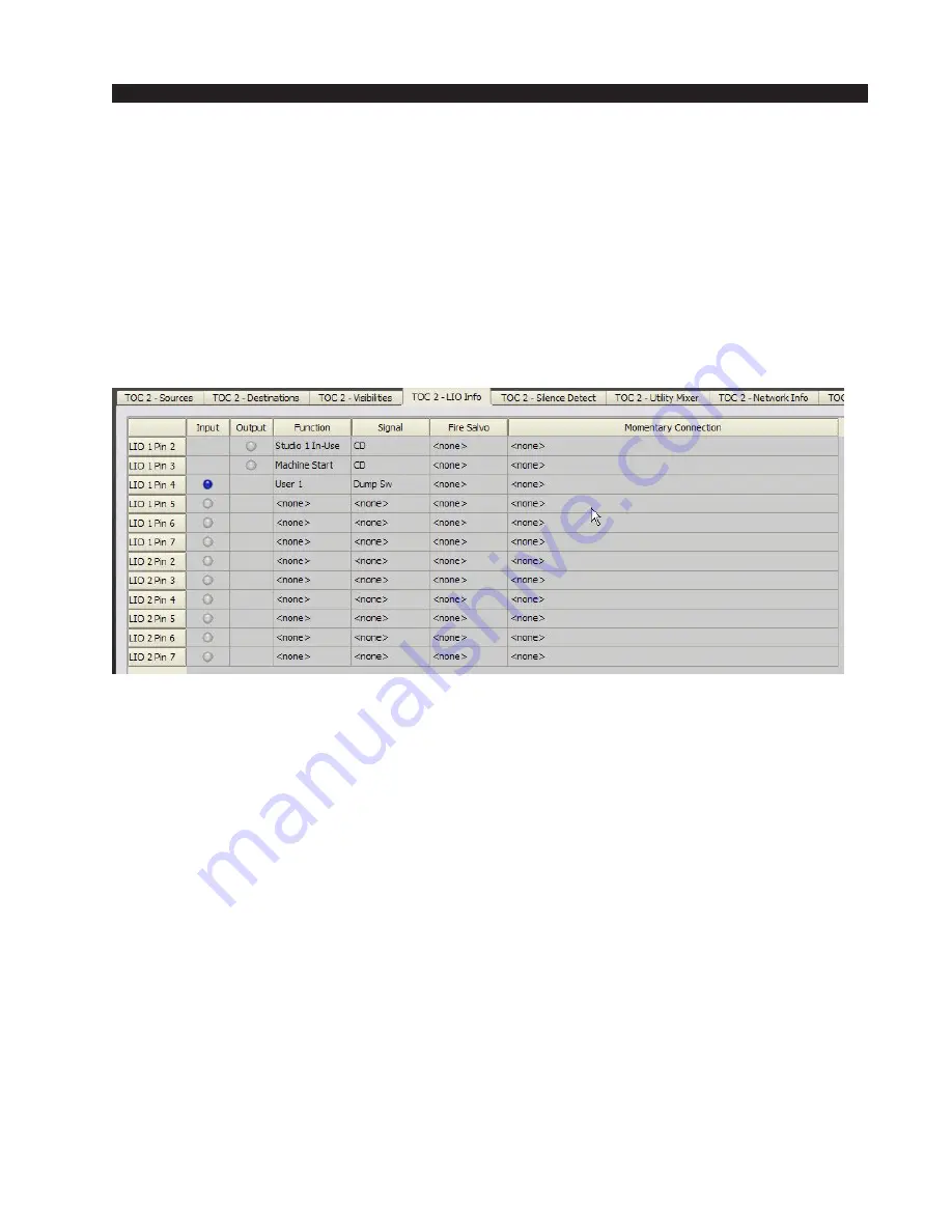
can use the WheatNet-IP Navigator GUI to trouble shoot this logic connection. Click
on the BLADE #5 icon in the System Pane and click on the LIO Info tab. The window
that opens will show the logic signals as they have been defined for the BLADE; you
should see your “Dump Sw” shown on line 3. If you have wired and mapped this
correctly, the circular indicator in the INPUT column for LIO #3 will change color every
time you press the switch. This tells you that the logic input has been wired correctly
and is working.
Likewise, if you click on the BLADE #19 icon and LIO Info tab, you should see the
“Dump Dev” logic signal shown on line 1. Again, if defined correctly and crosspoint
connected to the “Dump Sw” signal, the circular logic status indicator will change color
when you press the DUMP switch, showing activation of the logic signal at the output
port on the BLADE.
All discrete logic functions are defined and configured the same way. Once you’ve
made a few of them work to get comfortable with the process, it’s easy. Just remember
the fundamentals:
• Define the source and destination signals and map them to the logic ports you’ll use.
• Choose a matching pair of logic functions.
• Make a crosspoint connection between the source and destination signals (note, if
you want to, you can lock this connection just as you can audio signals).


