


0
Quick Reference of Parameters, Alarms and Faults
CFW501 | 0-19
0
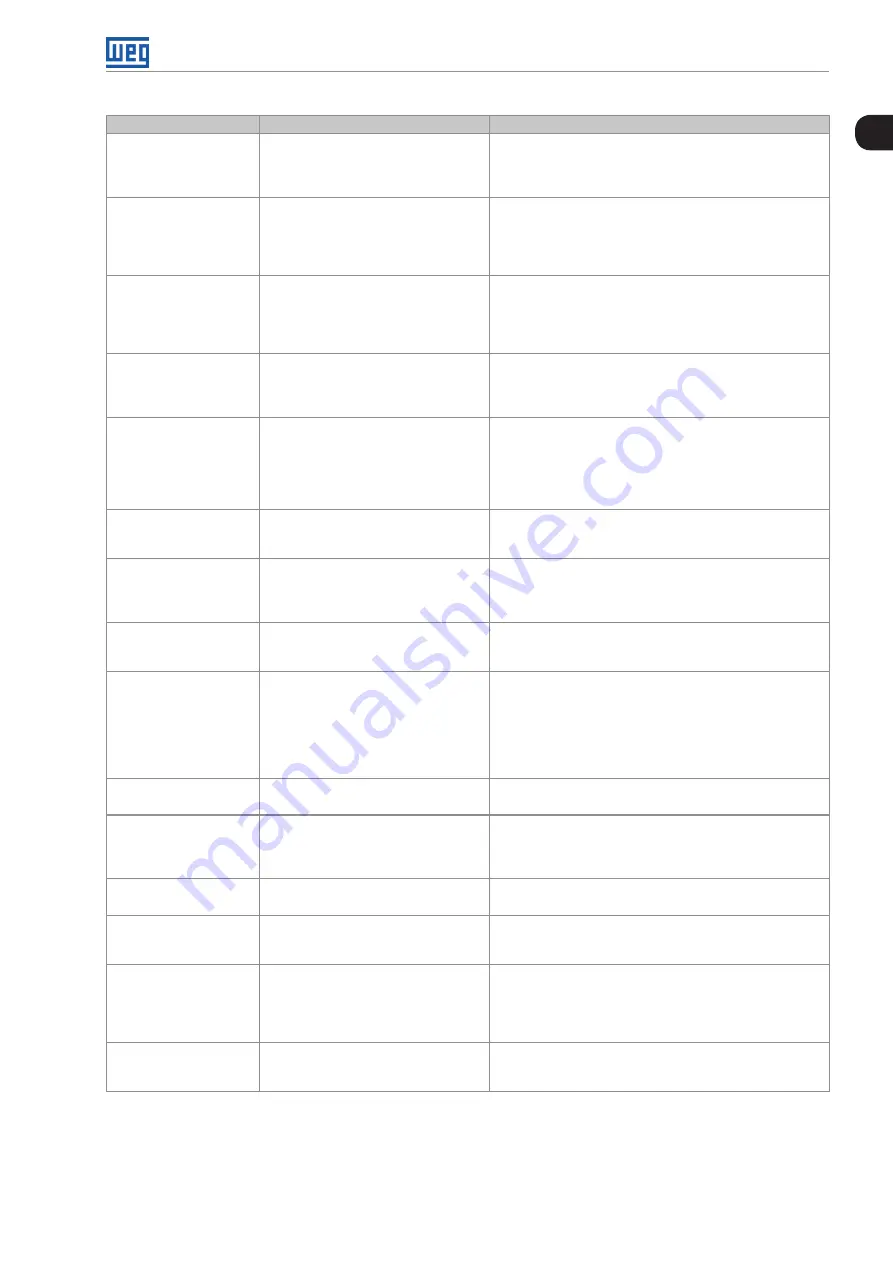
Fault / Alarm
Description
Possible Causes
F0031
Communication fault with
Plug-In module
Main control cannot set a communication
link with the Plug-In module.
Plug-In module is damaged.
Plug-In module is not properly connected.
Problem in the identification of the Plug-In module; refer to
P0027 for further information.
F0033
V V W self-tuning fault
Stator resistance setting fault P0409.
Stator resistance value in P0409 does not comply with the
inverter power.
Motor connection error; turn off the power supply and check the
motor terminal box and the connections with the motor terminals.
Motor power too low or too high in relation to the inverter.
F0048
Overload on the IGBTs
Overload fault on the power pack with
IGBTs (3 s in 1.5xInom).
Note:
This failure may be disabled, by setting
P0343 = 0 or 1.
Inverter output overcurrent (>2xInom).
F0051
IGBTs overtemperature
Overtemperature fault measured on the
temperature sensor of the power pack.
High ambient temperature around the inverter (>50 °C (>122 °F))
and high output current.
Blocked or defective fan.
Heatsink is too dirty, preventing the air flow.
F0070
Overcurrent/Short- circuit
Overcurrent or short- circuit on the
output, DC link or braking resistor.
Short- circuit between two motor phases.
Short- circuit of the rheostatic braking resistor connecting
cables.
IGBTs module in short- circuit or damaged.
Start with too short acceleration ramp.
Start with motor spinning without the flying-start function.
F0072
Motor overload
Motor overload fault (60 s in 1.5xInom)
P0156, P0157 and P0158 setting is too low in relation to the
motor operating current.
Overload on the motor shaft.
F0074
Ground fault
Ground overcurrent fault.
Note:
This failure may be disabled, by setting
P0343 = 0 or 2.
Short-circuit to the ground in one or more output phases.
Motor cable capacitance too high, causing current peaks in
the output.
F0076
Output Phase Current
Fault
This fault indicates the motor presents
phase loss, imbalanced phase current or
is disconnected.
Motor wiring or connection error.
Loss of motor connection with the drive or broken wire.
F0078
Motor overtemperature
Overtemperature fault measured on the
motor temperature sensor (Triple PTC)
via analog input AIx or digital input DIx.
Overload on the motor shaft.
Load cycle is too high (high number of starts and stops per
minute).
High ambient temperature around the motor.
Poor contact or short circuit (3.9 kΩ < R
PTC
< (100 Ω).
Motor thermistor not installed.
Motor shaft is stuck.
F0080
CPU fault (Watchdog)
Fault related to the supervision algorithm
of the inverter main CPU.
Electric noise.
Inverter firmware fault.
F0084
Auto-diagnosis fault
Fault related to the automatic identification
algorithm of the inverter hardware and
Plug-In module.
Poor contact in the connection between the main control and
the power pack.
Hardware not compatible with the firmware version.
Defect on the internal circuits of the inverter.
F0091
External fault
External fault via DIx (“No External Fault”
option in P0263 to P0270).
Wiring on DI1 to DI8 inputs are open or have poor contact.
F0182
Pulse feedback fault
Pulse feedback circuit fault of the output
voltage.
Note: it may be turned off in P0397.
Hardware identification fault; compare P0295 and P0296 to
the inverter identification label.
Inverter internal circuits fault.
F0228
Telegram reception
timeout
Serial communication timeout.
It indicates the equipment stopped
receiving valid serial telegrams for a
period longer than the setting in P0314.
Check network installation, broken cable or fault/poor contact
on the connections with the network, grounding.
Ensure the master always sends telegrams to the equipment
in a time shorter than the setting in P0314.
Disable this function in P0314.
F0700
Remote HMI
communication fault
No communication with remote HMI, but
there is speed command or reference for
this source.
Check if the communication interface with the HMI is properly
configured in parameter P0312.
HMI cable disconnected.
Summary of Contents for CFW501 V1.8X
Page 2: ......
Page 8: ...Summary...
Page 34: ...General Information 2 4 CFW501 2...
Page 38: ...About the CFW501 3 4 CFW501 3...
Page 42: ...HMI and Basic Programming 4 4 CFW501 4...
Page 58: ...Identification of the Inverter Model and Accessories 6 4 CFW501 6...
Page 72: ...Logical Command and Speed Reference 7 14 CFW501 7...
Page 76: ...Available Motor Control Types 8 4 CFW501 8...
Page 108: ...Functions Common to all the Control Modes 11 14 CFW501 11...
Page 134: ...Digital and Analog Inputs and Outputs 12 26 CFW501 12...
Page 148: ...Faults and Alarms 14 12 CFW501 14...