WEG CFW501 V1.8X Programming Manual Download Page 125

Digital and Analog Inputs and Outputs 

CFW501 | 12-17 

12

P0263 – Function of Digital Input DI1 

P0264 – Function of Digital Input DI2

P0265 – Function of Digital Input DI3

P0266 – Function of Digital Input DI4

P0267 – Function of Digital Input DI5

P0268 – Function of Digital Input DI6

P0269 – Function of Digital Input DI7

P0270 – Function of Digital Input DI8

Adjustable 

Range:

0 to 25

Factory 

Setting: 

P0263 = 1

P0264 = 0

P0265 = 20

P0266 = 21

P0267 = 0

P0268 = 0

P0269 = 0

P0270 = 0

Properties:

cfg

Access groups 

via HMI:

I/O 

Description:

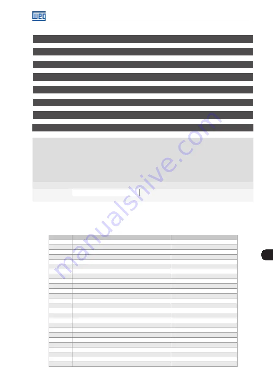
These parameters allow configuring the digital input function, according to the adjustable range listed i

Table 

12.8: Digital input functions on page 12-17

Table 12.8:

 Digital input functions

Value

Description

Dependence

0

Not Used

-

1

Run/Stop Command

P0224 = 1 or P0227 = 1

2

General Enable Command

P0224 = 1 or P0227 = 1

3

Quick Stop Command

P0224 = 1 or P0227 = 1

4

Forward/Reverse

P0223 = 4 or P0226 = 4

5

Local/Remote Selection

P0220 = 4

6

JOG

P0225 = 2 or P0228 = 2

7

SoftPLC

Prog. SoftPLC

8

2

nd

 Ramp Selection

P0105 = 2

9

Not Used

-

10

Not Used

-

11

Not Used

-

12

No External Alarm

-

13

No External Fault

-

14

Reset

Active fault

15

Disab. Flying-Start

P0320 = 1 ou 3

16

Not Used

-

17

Lock Programming 

-

18

Load User 1

Inverter disabled

19

Load User 2

Inverter disabled

20

Auto/Man main PID (1)

-

21

Auto/Man external PID (1)

-

22

Not Used

-

23

Bypass Mode

-

24

Activate Fire Mode

-

25

PTC

-

(1)

 For digital inputs DI5, DI6, DI7 and DI8, those options do not present associated functions.

Summary of Contents for CFW501 V1.8X

Page 1: ...Motors I Automation I Energy I Transmission Distribution I Coatings Frequency Inverter CFW501 V1 8X Programming Manual...

Page 2: ......

Page 3: ...Programming Manual Series CFW501 Language English Document Number 10002391560 01 Software Version 1 8X Publication Date 04 2015...

Page 4: ...ry of Reviews The information below describes the reviews made in this manual Version Review Description V1 5X R00 First edition V1 8X R01 New options of the V f and VVW Control Type included and modi...

Page 5: ...GRAMMING AND SETTINGS 5 1 5 1 PARAMETER STRUCTURE 5 1 5 2 PARAMETERS SELECTED BY THE HMI MENU 5 1 5 3 HMI 5 2 5 4 INDIRECT ENGINEERING UNITS 5 6 5 5 BACKUP PARAMETERS 5 11 5 6 SETTING OF DISPLAY INDIC...

Page 6: ...LOG INPUTS AND OUTPUTS 12 1 12 1 ANALOG INPUTS 12 1 12 2 ANALOG OUTPUTS 12 7 12 3 FREQUENCY INPUT 12 10 12 4 FREQUENCY OUTPUT 12 13 12 5 DIGITAL INPUTS 12 15 12 6 DIGITAL OUTPUT 12 22 13 RHEOSTATIC BR...

Page 7: ...UNICATION COMMANDS AND STATUS 16 2 17 SOFTPLC 17 1 18 HVAC FUNCTIONS 18 1 18 1 ENERGY SAVING 18 1 18 2 PROTECTION AGAINST SHORT CYCLES 18 3 18 3 DRY PUMP 18 4 18 4 BROKEN BELT 18 6 18 5 FILTER MAINTEN...

Page 8: ...Summary...

Page 9: ...0010 Output Power 0 0 to 6553 5 kW ro READ 15 3 P0011 Power Factor 1 00 to 1 00 ro READ 15 3 P0012 DI8 to DI1 Status Bit 0 DI1 Bit 1 DI2 Bit 2 DI3 Bit 3 DI4 Bit 4 DI5 Bit 5 DI6 Bit 6 DI7 Bit 7 DI8 ro...

Page 10: ...037 Motor Overload Ixt 0 to 100 ro READ 14 3 P0042 Powered Time 0 to 65535 h ro READ 15 5 P0043 Enabled Time 0 0 to 6553 5 h ro READ 15 5 P0044 kWh Output Energy 0 to 65535 kWh ro READ 15 6 P0047 CONF...

Page 11: ...BASIC MOTOR 9 4 P0137 Autom Torque Boost 0 0 to 30 0 0 0 V f MOTOR 9 6 P0138 Slip Compensation 10 0 to 10 0 0 0 V f MOTOR 9 7 P0139 Output Current Filter 0 to 9999 ms 50 ms 8 1 P0140 Sleep Compensatio...

Page 12: ...condary Parameter Display 0 to 1079 1 HMI 5 3 P0208 Main Display Scale Factor 0 1 to 1000 0 100 0 HMI 5 4 P0209 Main Display Eng Unit 0 None 1 V 2 A 3 rpm 4 s 5 ms 6 None 7 m 8 None 9 None 10 11 C 12...

Page 13: ...221 LOC Reference Sel 0 Keypad 1 AI1 2 AI2 3 AI3 4 AI1 AI2 0 5 AI1 AI2 6 Serial USB 7 SoftPLC 8 FI 9 AI1 0 10 AI2 0 11 AI3 0 12 FI 0 0 cfg I O 7 5 P0222 REM Reference Sel See options in P0221 1 cfg I...

Page 14: ...AI2 Offset 100 0 to 100 0 0 0 I O 12 4 P0240 AI2 Filter 0 00 to 16 00 s 0 15 s I O 12 5 P0241 AI3 Signal Function See options in P0231 0 cfg I O 12 3 P0242 AI3 Gain 0 000 to 9 999 1 000 I O 12 4 P024...

Page 15: ...ut 17 Not Used 18 P0698 Value 15 I O 12 14 P0258 FO Gain 0 000 to 9 999 1 000 I O 12 15 P0259 Min FO 10 to 20000 Hz 10 Hz I O 12 15 P0260 Max FO 10 to 20000 Hz 10000 Hz I O 12 15 P0263 DI1 Function 0...

Page 16: ...9 4 20 mA OK 20 P0695 Value 21 Forward 22 Ride Through 23 Pre Charge OK 24 Fault 25 Time Enable Hx 26 SoftPLC 27 Not Used 28 F Fx 1 29 F Fx 2 30 Not Used 31 Not Used 32 No Alarm 33 No Fault Alarm 34 D...

Page 17: ...12 P0302 DC Braking Voltage 0 0 to 100 0 20 0 MOTOR 11 12 P0303 Skip Speed 1 0 to 18000 rpm 600 rpm 11 13 P0304 Skip Speed 2 0 to 18000 rpm 900 rpm 11 13 P0306 Skip Band 0 to 18000 rpm 0 rpm 11 13 P03...

Page 18: ...525 V P0296 2 cfg MOTOR STARTUP 10 5 P0401 Motor Rated Current 0 to 200 0 A 1 0xInom cfg MOTOR STARTUP 10 6 P0402 Motor Rated Speed 0 to 30000 rpm 1710 1425 rpm cfg MOTOR STARTUP 10 6 P0403 Motor Rat...

Page 19: ...14 None 15 h 16 W 17 kW 18 None 19 None 20 min 21 F 22 bar 23 mbar 24 psi 25 Pa 26 kPa 27 MPa 28 mwc 29 mca 30 gal 31 l 32 in 33 ft 34 m3 35 ft3 36 gal s 37 gal min 38 gal h 39 l s 40 l min 41 l h 42...

Page 20: ...AC 18 3 P0586 Minimum RUN Time 0 to 650 00 s 5 00 s cfg HVAC 18 4 P0587 Minimum STOP Time 0 00 to 650 00 s 5 00 s cfg HVAC 18 4 P0588 Energy Saving Max Torque 0 to 85 60 cfg V f HVAC 18 2 P0589 Energy...

Page 21: ...T 16 2 P0765 Token RX Qtde 0 to 65535 ro NET 16 2 P1000 SoftPLC Status 0 No Applicative 1 Installing App 2 Incompatible App 3 Stopped App 4 App Running ro HVAC 17 1 P1001 SoftPLC Command 0 Stop Applic...

Page 22: ...2 18 15 P1031 Main PID Feedback Alarm Low V 32768 to 32767 50 HVAC 17 2 18 15 P1032 Main PID Feedback Alarm Low T 0 00 to 650 00 s 5 00 s HVAC 17 2 18 16 P1033 Main PID Feedback Alarm High V 32768 to...

Page 23: ...nal PID Man Setpoint 0 0 to 100 0 0 0 HVAC 17 2 18 20 P1062 External PID Feedback 32768 to 32767 ro HVAC 17 2 18 21 P1063 External PID Output 0 0 to 100 0 ro HVAC 17 2 18 21 P1064 External PID Action...

Page 24: ...rnal PID Feedback Alarm Low T 0 00 to 650 00 s 5 00 s HVAC 17 2 18 26 P1078 External PID Feedback Alarm High V 32768 to 32767 900 HVAC 17 2 18 27 P1079 External PID Feedback Alarm High T 0 00 to 650 0...

Page 25: ...le command is disabled Check if the drive general enable command is active A0704 Two movem enabled It occurs when 2 or more SoftPLC movement blocks REF Block are enabled at the same time Check the use...

Page 26: ...iable of the External PID Controller Alarm that indicates an analog input was not programmed for the process variable of the external PID controller Parameter P0231 or P0236 was not programmed for 8 A...

Page 27: ...the output F0076 Output Phase Current Fault This fault indicates the motor presents phase loss imbalanced phase current or is disconnected Motor wiring or connection error Loss of motor connection wit...

Page 28: ...for the time programmed in P1045 F0769 Broken Belt Detected Fault that indicates the broken belt condition was detected for the motor driven by the CFW501 frequency inverter Parameter P1046 is program...

Page 29: ...MANUAL DANGER The procedures recommended in this warning have the purpose of protecting the user against death serious injuries and considerable material damage ATTENTION The procedures recommended in...

Page 30: ...ages and or moving fans even after the AC power supply input is disconnected or turned off Wait for at least ten minutes in order to guarantee the full discharge of the capacitors Always connect the f...

Page 31: ...rpm NOTE The specific HVAC functions present on the CFW501 can only be activated with the connection of the HVAC plug in module CFW500 CRS485 Other plug in modules can be used but in this case the HV...

Page 32: ...ed the PWM pulses will be immediately blocked It may be controlled by digital input set for this function or via serial Run Stop inverter function which when activated run accelerates the motor by acc...

Page 33: ...nit of measurement of rotation s second V volts ohms 2 2 2 Numerical Representation The decimal numbers are represented by means of digits without suffix Hexadecimal numbers are represented with the l...

Page 34: ...General Information 2 4 CFW501 2...

Page 35: ...er losses by adjusting the V f curve using the parameters based on quadratic curve approximation of the V f relationship which results in energy saving The V f mode is used when more than a motor is a...

Page 36: ...k capacitor bank Braking IGBT available in Inverters CFW501 DB HMI CPU 32 bits RISC EEPROM memory User s plug in card Interface RS 485 Analog output AO1 Supply 24 V Supply 10 V Digital output DO1 RL1...

Page 37: ...CFW501 CFW501 3 3 3 3 4 5 2 6 1 1 Fixing support for surface mounting 2 Fixing support for Din rail mount 3 Fan with fixing support 4 Plug in module 5 HMI 6 Front cover Figure 3 2 Main components of t...

Page 38: ...About the CFW501 3 4 CFW501 3...

Page 39: ...l the new value new value is not saved and return to level 2 of the setting mode When in the monitoring mode press this key to increase the speed When in the setting mode level 1 press this key to go...

Page 40: ...ct the parameter groups only one parameter group is shown at a time Main display Forward Reverse Figure 4 2 Display areas Parameter groups available in the field Menu PARAM all parameters READ read on...

Page 41: ...the parameter group using the keys and The fields main display secondary display bar graph for monitoring of variable and measurement units are not shown in this level Press the ENTER MENU key to go...

Page 42: ...HMI and Basic Programming 4 4 CFW501 4...

Page 43: ...re different from the factory settings BASIC Parameters for simple application ramps minimum and maximum speed maximum current and torque boost P0100 P0101 P0133 P0134 P0135 P0136 MOTOR Parameter rela...

Page 44: ...MI In the HMI group you find parameters related to the showing of information on the display backlight and password of the HMI See detailed description below of the possible settings of the parameters...

Page 45: ...00 P0200 new password 3 After this procedure the new password is active and P0200 is automatically adjusted for 1 password active 1 Disable password 1 Set the current value of the password P0000 passw...

Page 46: ...the Main Display P0212 Indication Form of the Second Display Adjustable Range 0 wxyz 1 wxy z 2 wx yz 3 w xyz 4 According to P0511 5 According to P0513 6 Reserved 7 According to P0517 Factory Setting 0...

Page 47: ...m 35 ft 36 gal s 37 gal min 38 gal h 39 l s 40 l min 41 l h 42 m s 43 m min 44 m h 45 ft s 46 ft min 47 ft h 48 m s 49 m min 50 m h 51 ft s 52 ft min 53 ft h 54 According to P0510 55 According to P05...

Page 48: ...off and parameter P0216 starts to control the remote HMI 5 4 INDIRECT ENGINEERING UNITS This parameter group allows the user to configure the engineering units for the user s parameters of the SoftPL...

Page 49: ...nd P1033 of the main PID controller HVAC functions are associated to the indirect engineering unit 1 P0511 Indirect Indication Form 1 Adjustable Range 0 wxyz 1 wxy z 2 wx yz 3 w xyz Factory Setting 1...

Page 50: ...43 m min 44 m h 45 ft s 46 ft min 47 ft h 48 m s 49 m min 50 m h 51 ft s 52 ft min 53 ft h Properties Access groups via HMI HMI Description This parameter selects the engineering unit that will be vi...

Page 51: ...that is associated to the indirect indication form 2 will be viewed in this format on the CFW501 HMI NOTE Parameters P1011 P1015 P1027 P1028 P1031 and P1033 of the main PID controller HVAC functions...

Page 52: ...the CFW501 HMI NOTE Parameters P1036 P1043 and P1047 are related to speed limits Hz or rpm in the HVAC functions and are associated to the indirect engineering unit 4 P0517 Indirect Indication Form 4...

Page 53: ...rameters on the inverter with the factory default for 60 Hz 6 Load WEG 50 Hz It loads the default parameters on the inverter with the factory default for 50 Hz 7 Load user 1 It transfers the content o...

Page 54: ...d for LOC REM selection 5 9 Two or more DIx P0263 P0270 programmed for 2nd ramp 8 11 Two or more DIx P0263 P0270 programmed for disable Flying Start 15 12 Two or more DIx P0263 P0270 programmed for lo...

Page 55: ...e Those data are on the EEPROM memory located on the control board P0027 Plug in Module Configuration Adjustable Range 0 to 9 Factory Setting Properties ro Access groups via HMI READ Description This...

Page 56: ...0 480 V Three Phase 1 0 A A 6 380 480 V Three Phase 1 6 A A 7 380 480 V Three Phase 2 6 A A 8 380 480 V Three Phase 4 3 A A 9 380 480 V Three Phase 6 1 A A 10 200 240 V Single Phase or Three Phase 7 3...

Page 57: ...o 15000 Hz Factory Setting 5000 Hz Properties Access groups via HMI MOTOR Description You can use this parameter to define the inverter IGBT switching frequency Theinverterswitchingfrequencymaybeadjus...

Page 58: ...Identification of the Inverter Model and Accessories 6 4 CFW501 6...

Page 59: ...7 7 1 SELECTION FOR LOGICAL COMMAND AND SPEED REFERENCE The inverter command and reference source is defined by the inverter parameters for two different situations local and remote which can be switc...

Page 60: ...REM JOG JOG Run Run Stop Stop Direction Direction of rotation of rotation Control Control word word REM REM LOC LOC P0220 P0228 P0227 P0224 P0226 P0223 P0225 P0105 P0221 P0222 All of the inverter com...

Page 61: ...al Command and Speed Reference CFW501 7 3 7 Command selection P0105 and P0223 to P0228 HMI Keys Dlx Serial USB SoftPLC SoftPLC HMI CRS485 P0312 Inverter control word Figure 7 2 Command selection struc...

Page 62: ...eference key P0121 FI Frequency input 0 HMI Keys 8 FI 12 FI 0 HMI AI1 1 AI1 9 AI1 0 2 AI2 10 AI2 0 4 AI1 AI2 0 5 AI1 AI2 AI2 CRS485 Inverter speed reference 6 Serial or USB SoftPLC 7 SoftPLC P0239 P02...

Page 63: ...in P0263 to P0270 P0221 Speed Reference Selection LOCAL Situation P0222 Speed Reference Selection REMOTE Situation Adjustable Range 0 HMI Keys 1 AI1 2 AI2 3 AI3 4 AI1 AI2 0 Sum AIs 0 5 AI1 AI2 Sum AIs...

Page 64: ...where H it means clockwise default at the inverter power up AH means counterclockwise default at the inverter power up DIx refer to section 12 5 DIGITAL INPUTS on page 12 15 P0224 Run Stop Selection L...

Page 65: ...with signal with a full scale in 18000 rpm and resolution of 0 55 rpm The speed reference via HMI can be the JOG key of the keys and on parameter P0121 In digital inputs DIx on the other hand the refe...

Page 66: ...e Range 0 Inactive 1 Active 2 Backup by P0121 Factory Setting 1 Description This parameter defines the operation of the speed reference backup function between the options active P0120 1 inactive P012...

Page 67: ...LOGICAL COMMAND AND SPEED REFERENCE on page 7 1 The direction of rotation is defined by parameters P0223 LOCAL or P0226 REMOTE The JOG command is only effective with the motor stopped 7 2 4 Analog Inp...

Page 68: ...D Status Run Stop 0 There was no Run command 1 There was Run command 2 Fire mode 0 Fire mode Inactive 1 Fire mode Active 3 Bypass 0 Bypass Inactive 1 Bypass Active 4 Quick Stop 0 Quick stop inactive 1...

Page 69: ...acceleration 1 Inverter accelerating 8 Freeze Ramp 0 Ramp operating in normal conditions 1 The path of the ramp is frozen by some command source or internal function 9 Setpoint Ok 0 Output frequency h...

Page 70: ...e 1 Enable General 0 Disable the inverter completely interrupting the power supply to the motor 1 Enable completely the inverter allowing the operation of the motor 2 Run Clockwise 0 Run the motor in...

Page 71: ...owing the command P0229 via HMI to be able to disable the motor by inertia instead of deceleration ramp In this way when P0229 1 bit 0 of the control word Ramp Enable has a function similar to bit 1 G...

Page 72: ...Logical Command and Speed Reference 7 14 CFW501 7...

Page 73: ...ensorless Vector Control for applications that need high performance in the control of the output speed In chapter 9 V f SCALAR CONTROL on page 9 1 and chapter 10 VVW VECTOR CONTROL on page 10 1 each...

Page 74: ...plied to the motor which can cause torque reduction at low speeds and current oscillation in motors above 5 HP running with no load Thus the dead time compensation measures the voltage pulse width in...

Page 75: ...bled Disabled Enabled Disabled 0003h Disabled Disabled Enabled Enabled 0004h Disabled Enabled Disabled Disabled 0005h Disabled Enabled Disabled Enabled 0006h Disabled Enabled Enabled Disabled 0007h Di...

Page 76: ...Available Motor Control Types 8 4 CFW501 8...

Page 77: ...ive output current and the DC link voltage compensators and controllers which help protect the V f control performance are implemented The operation and parameterization of those blocks are detailed i...

Page 78: ...tion of rotation PWM I o I o I o i V i W i V i W i V i W I a Zero Calculation of I a Calculation of I o Hold P0135 P0151 P0151 P0152 P0004 P0151 P0003 P0011 P0138 P0137 P0134 P0142 P0143 P0144 P0136 P...

Page 79: ...P1 P2 P3 P4 P0142 P0143 P0144 P0136 Output frequency Hz Output voltage Figure 9 2 Curve V f The CFW501 factory default settings define a linear relationship of the torque with the speed overlapping po...

Page 80: ...he torque constant The optimum setting is the smallest value of P0136 which allows the motor satisfactory start A value greater than necessary will excessively increase the motor current at low speeds...

Page 81: ...o 18000 Factory Setting P0145 1800 1500 rpm P0146 1200 1000 rpm P0147 600 500 rpm Properties cfg V f Description These parameters allow adjusting the inverter V f curve together with its orderly pairs...

Page 82: ...to the output active current in relation to the maximum current 2xP0295 The setting criteria of P0137 are the same as those of P0136 that is set the value as low as possible for the motor start and o...

Page 83: ...re 9 1 Block diagram of V f scale control on page 9 2 this compensation is represented in the variable fSlip The setting in P0138 allows regulating with good accuracy the slip compensation by moving t...

Page 84: ...t rated frequency power supply of the inverter used 4 In order to set a V f curve different from the default set the V f curve using parameters P0136 to P0147 5 Setting of specific parameters and func...

Page 85: ...Besides the VVW control has a quick and simple setting and it is suitable for most medium performance applications in the control of three phase induction motor By just measuring the output current t...

Page 86: ...I o I o i V i W i V i W i V i W I a I a I o f o m I a I o Zero Filter Calculation of I a Calculation of f slip Torque estimation Calculation of I o Hold P0135 P0151 P0151 P0152 P0140 P0403 P0295 P295...

Page 87: ...10 1 Characteristics of IV pole WEG standard motors Power P0404 Frame Voltage P0400 V Current P0401 A Frequency P0403 Hz Speed P0402 rpm Efficiency P0399 Power Factor P0407 Stator Resistance P0409 CV...

Page 88: ...3 1 00 0 75 80 1 86 1395 72 0 0 81 12 85 1 50 1 10 90S 2 61 1420 77 0 0 79 7 73 2 00 1 50 90L 3 34 1410 79 0 0 82 5 06 3 00 2 20 100L 4 75 1410 81 5 0 82 2 95 4 00 3 00 100L 6 47 1400 82 6 0 81 1 75 5...

Page 89: ...Table 10 2 Default setting of P0400 according to the identified inverter model on page 10 5 Properties cfg Access groups via HMI MOTOR STARTUP Description Set according to the data on the motor namepl...

Page 90: ...g 60 Hz 50 Hz Properties cfg Access groups via HMI MOTOR STARTUP P0404 Motor Rated Power Adjustable Range 0 0 16 hp 0 12 kW 1 0 25 hp 0 19 kW 2 0 33 hp 0 25 kW 3 0 50 hp 0 37 kW 4 0 75 hp 0 55 kW 5 1...

Page 91: ...measure the stator resistance If the estimated value of the motor stator resistance is too high for the inverter used for example motor not connected or motor too small for the inverter the inverter...

Page 92: ...available insert the approximate value by calculation or similarity to WEG standard motor see Table 10 1 Characteristics of IV pole WEG standard motors on page 10 3 7 Self Tuning of the VVW control T...

Page 93: ...ess ENTER MENU and with the and keys set the value 3 which activates VVW control mode If necessary modify the content of P0401 Motor rated current or press the key for the next parameter 5 10 Press EN...

Page 94: ...ESC 14 19 At this point the HMI shows the option to do the Self Tuning Whenever possible execute the self tuning To activate the self tuning change the value of P0408 to 1 By means of the and keys se...

Page 95: ...ost functions 2nd Ramp it may be activated by the user according to the drive requirement by means of the inverter command word or by a digital input 3rd Ramp it is used for the inverter protection fu...

Page 96: ...escription Deceleration time from maximum speed P0134 to zero when the 2nd ramp is active P0104 S Ramp Adjustable Range 0 Inactive 1 Active Factory Setting 0 Properties cfg Description This parameter...

Page 97: ...aining the voltage increase in the DC link and output current In this way the following of the reference by the ramp is blocked and the output speed follows the 3rd ramp for P0133 or P0134 When the DC...

Page 98: ...4 Block diagram of DC link voltage limitation Accelerate Ramp P0152 1 or P0152 3 on page 11 6 and Figure 11 5 Example graph of the DC ling voltage limitation Accelerate Ramp P0152 1 or P0152 3 on page...

Page 99: ...ue of P0152 is multiplied by the error of the DC link voltage seeing that the error results from the difference between the actual DC link voltage P0004 and the actuation level of the DC link voltage...

Page 100: ...nk regulation Time Time Ud P0151 Output speed Figure 11 3 Example graph of DC link voltage limitation Ramp Hold P0152 0 or P0152 2 Ramp Reference Output speed Error P0001 P0004 P0151 P0152 P0152 x err...

Page 101: ...torque overload in the acceleration or deceleration Actuation if the motor current exceeds the value set in P0135 during acceleration or deceleration the speed will not be incremented acceleration or...

Page 102: ...on for the ramp hold and decelerate ramp modes as per Figure 11 6 a and b Actuation modes of current limitation via P0135 on page 11 8 respectively t s t s t s t s t s t s Acceleration Ramp accelerati...

Page 103: ...the following sections P0331 Voltage Ramp for FS and RT Adjustable Range 0 2 to 60 0 s Factory Setting 2 0 s Description This parameter determines the rising time of the output voltage during the exe...

Page 104: ...gure 11 7 Actuation of the Ride Through function on page 11 10 DC link voltage F021 Level Output pulses tdesab tdead Enabled Disabled Return line Output voltage 0 V 0 rpm Output speed P0002 P0331 Figu...

Page 105: ...where the dead time for the de magnetization of the motor can be observed This time is proportional to the speed at the moment of the injection of direct current Injection of DC current Output speed D...

Page 106: ...to 100 0 Factory Setting 20 0 Properties Access groups via HMI MOTOR Description This parameter sets the DC voltage DC braking torque applied to the motor during the braking The setting must be done...

Page 107: ...P0304 Skip Speed 2 P0306 Skip Band Adjustable Range 0 to 18000 rpm Factory Setting P0303 600 rpm P0304 900 rpm P0306 0 rpm Properties Description The actuation of those parameters is done as presente...

Page 108: ...Functions Common to all the Control Modes 11 14 CFW501 11...

Page 109: ...n module connected to the product 12 1 ANALOG INPUTS With the analog inputs it is possible for instance to use an external speed reference or to connect a sensor in order to measure temperature PTC De...

Page 110: ...ge 12 2 If the parameter is configured as Active P0230 1 the signal in the analog inputs will have a dead zone where the speed reference remains at the Minimum Speed value P0133 even with the variatio...

Page 111: ...to P0103 However in order to do so it is also necessary to configure parameters P0221 and or P0222 by selecting the use of the desired analog input For further detail refer to the description of thos...

Page 112: ...eedback of the External PID controller NOTE In options 5 to 8 in case two or more analog inputs are selected for the same function for instance P0231 5 and P0236 5 only the analog input with higher pr...

Page 113: ...diagram of the analog inputs Aix on page 12 5 Input AI1 AI2 AI3 Gain AI1 P0232 AI2 P0237 AI3 P0242 OFFSET AI1 P0234 AI2 P0239 AI3 P0244 AI1 P0235 AI2 P0240 AI3 P0245 AI1 P0018 AI2 P0019 AI3 P0020 Func...

Page 114: ...nd equation Signal P0233 P0238 P0243 DIP Switch Equation AIx 0 to 10 V 0 0 OFF AIx x 100 Offset x Gain AIx V 10 V 0 to 20 mA 0 0 ON AIx x 100 Offset x Gain AIx mA 20 mA 4 to 20 mA 1 1 ON AIx x 100 Off...

Page 115: ...P0037 P0696 P0697 P0698 Value AOx AO1 AO2 Signal AO1 P0253 AO2 P0256 Control terminals available in the Plug In module Figure 12 3 Block diagram of Analog outputs AOx P0014 Analog Output AO1 Value P0...

Page 116: ...ull scale of analog outputs on page 12 8 Table 12 3 Full scale of analog outputs Function Description Full Scale 0 Speed reference in the ramp input P0001 P0134 2 Real speed in the inverter output P00...

Page 117: ...eters it is also necessary to position the DIP switches Refer to the installation configuration and operation guide of the used plug in module Table 12 5 Characteristic configuration and equations of...

Page 118: ...parameter P0022 shows the frequency of the pulses in Hz From this conversion step the signal in frequency receives a treatment similar to that of a regular analog input compare to Figure 12 2 Block di...

Page 119: ...in Hz Adjustable Range 0 to 20000 Hz Factory Setting Properties ro Access groups via HMI READ I O Description Value in hertz of the frequency input FI NOTE The operation of parameters P0021 and P0022...

Page 120: ...250 P0248 Parameters P0248 and P0250 determine the operation range of the frequency input FI while parameters P0249 and P0247 for offset and gain respectively For example FI 5000 Hz P0248 10 Hz P0250...

Page 121: ...1 P0009 SoftPLC P0037 P0696 P0697 P0698 Value FO DO2 100 FO FO P0016 FO Hz P0017 FO Hz Calc Hz Hz P0259 P0260 Control terminal available in the Plug In module Figure 12 5 Block diagram of the output i...

Page 122: ...is inactive that is P0257 15 However any other option of P0257 and the digital output DO2 becomes the frequency output ignoring the digital output function set in P0276 Table 12 6 Full scale of frequ...

Page 123: ...use the digital inputs the CFW501 features up to eight ports depending on the plug in module connected to the product Check Table 12 1 I O Configurations of the CFW501 on page 12 1 Below is a detailed...

Page 124: ...s if BIT0 is 0 DI1 is inactive if BIT0 is 1 DI1 is active and so on up to DI8 Besides the determination of DIx active or inactive takes into account the signal type in the DIx defined by P0271 The act...

Page 125: ...2 8 Digital input functions on page 12 17 Table 12 8 Digital input functions Value Description Dependence 0 Not Used 1 Run Stop Command P0224 1 or P0227 1 2 General Enable Command P0224 1 or P0227 1 3...

Page 126: ...NERAL ENABLE It enables the inverter spin through the acceleration ramp and disables it by cutting off the pulses immediately the motor stops by inertia Aceleration ramp Motor runs free Time Time Acti...

Page 127: ...9 Example of the direction of rotation function e LOCAL REMOTE If DIx is inactive the local command is selected otherwise the remote command is selected f JOG The JOG command is the combination of th...

Page 128: ...status Dix in P0012 is used for the SoftPLC functions l Automatic Manual for Main PID configures the input to select the operating mode of the Main PID Controller being automatic with the application...

Page 129: ...e that the user is loaded from a transition in the DIx programmed for this function q LOAD Us 2 This function allows selecting the user 2 memory process similar to P0204 8 with the difference that the...

Page 130: ...g Properties ro Access groups via HMI READ I O Description By using this parameter it is possible to view the CFW501 digital output status The value of P0013 is indicated in hexadecimal where each bit...

Page 131: ...l to 1 or 3 and AIx 2 mA 20 P0695 Value Status of the bits 0 to 4 of P0695 activate digital outputs DO1 to DO5 respectively 21 Clockwise Active if the inverter direction of rotation is Clockwise 22 Ri...

Page 132: ...P0289 Ny Speed Adjustable Range 0 to18000 rpm Factory Setting P0288 120 100 rpm P0289 1800 1500 rpm Properties Access groups via HMI I O Description These parameters set the hysteresis and actuation...

Page 133: ...s groups via HMI I O Description It is used in the N N function of the digital and relay outputs P0293 Tx Torque Adjustable Range 0 to 200 Factory Setting 100 Properties Access groups via HMI I O Desc...

Page 134: ...Digital and Analog Inputs and Outputs 12 26 CFW501 12...

Page 135: ...regenerated energy On the other hand if the level is too lower than the overvoltage the function limits the actuation at a maximum of 15 of the overvoltage level Thus it is ensured that the braking r...

Page 136: ...nverter powered down connect the braking resistor refer to the user s manual item 3 2 Electric Installations Setting P0151 for the maximum value 410 V P0296 0 810 V P0296 1 or 1200 V P0296 2 according...

Page 137: ...on fault and alarm codes are F0072 and A0046 respectively The motor overload is given considering the reference value In x FS motor rated current multiplied by the duty factor which is the maximum val...

Page 138: ...above 50 it is P0156 The greater the difference between the motor current and the overload current P0156 P0157 or P0158 the faster the actuation of fault F0072 It is recommended that parameter P0156...

Page 139: ...the overload alarm is inactive P0037 Overload of Motor Ixt Adjustable Range 0 to 100 Factory Setting Properties ro Access groups via HMI READ Description This parameter indicates the present motor ov...

Page 140: ...e value programmed in P0349 The IGBTs overload protection can be disabled through parameter P0343 0 5 10 15 20 25 30 3 2 5 2 1 5 1 0 5 0 Output current Overload current Region of overload Time s Figur...

Page 141: ...those values are exceeded fault F0078 is indicated as shown in Table 14 1 Actuation level of fault F0078 PTC via analog input on page 14 5 ATTENTION The PTC must feature reinforced insulation of the...

Page 142: ...105 C 10 A 400 V 110 C Frame C 24 A 200 V 120 C 14 A 400 V 110 C 16 A 400 V 110 C Besides the alarm indication A0050 the overtemperature protection automatically reduces the switching frequency P0297...

Page 143: ...501 terminals and parameter P0312 being programmed for interface with remote HMI a supervision of the communication with the HMI is activated so that alarm A0700 is activated whenever this communicati...

Page 144: ...FEEDBACK FAULT F0182 When the dead time compensation is active in P0397 refer to chapter 8 AVAILABLE MOTOR CONTROL TYPES on page 8 1 and the pulse feedback circuit has some defect fault F0182 will oc...

Page 145: ...nk Last Fault P0062 DC Link Second Fault P0072 DC Link Third Fault Adjustable Range 0 to 2000 V Factory Setting Properties ro Access groups via HMI READ Description They indicate the DC link voltage a...

Page 146: ...Second Fault P0075 Logical Status Third Fault Adjustable Range 0000h to FFFFh Factory Setting Properties ro Access groups via HMI READ Description It records the inverter logical status of P0680 at th...

Page 147: ...ting of P0340 NOTE The auto reset is locked if the same fault occurs three times in a row within 30 seconds after the reset P0340 Auto Reset Time Adjustable Range 0 to 255 s Factory Setting 0 s Descri...

Page 148: ...Faults and Alarms 14 12 CFW501 14...

Page 149: ...esents regardless of the origin source the speed reference value in rpm factory setting P0002 Output Speed Motor Adjustable Range 0 to 65535 rpm Factory Setting Properties ro Access groups via HMI REA...

Page 150: ...tatus is presented as well as the indication on the HMI Table 15 1 Inverter status P0006 P0006 Status HMI Description 0 Ready Indicates the inverter is ready to be enabled 1 Run Indicates the inverter...

Page 151: ...5 kW Factory Setting Properties ro Access groups via HMI READ Description It indicates the electric power in the inverter output This power is determined through the formula P0010 3 x P0003 x P0007 x...

Page 152: ...in P0017 Frequency Output Value FO in Hz Refer to section 12 4 FREQUENCY OUTPUT on page 12 13 P0018 Analog Input Value AI1 P0019 Analog Input Value AI2 P0020 Analog Input Value AI3 Refer to section 1...

Page 153: ...Setting Properties ro Access groups via HMI READ Description It indicates the total number of hours that the inverter remained powered This value is kept even when power is removed from the inverter...

Page 154: ...is calculated indirectly and must not be used to measure the energy consumption P0047 CONF Status Adjustable Range 0 to 999 Factory Setting Properties ro Access groups via HMI READ Description This pa...

Page 155: ...interface CFW500 CRS485 plug in module as per the figures below Figure 16 1 Plug In Module CFW500 CRS485 NOTE The CFW500 CRS485 plug in module has Serial 1 interface through RS485 port at terminals 12...

Page 156: ...on refer to Metasys N2 user s manual supplied on the CD ROM that comes with the product 16 4 COMMUNICATION COMMANDS AND STATUS P0313 Action for Communication Error P0680 Logical Status P0681 Speed in...

Page 157: ...uploaded to the flash memory board is not compatible with the present CFW501 firmware In this case it is necessary that the user recompile the project on the WLP considering the new CFW501 version and...

Page 158: ...OTE One part of the HVAC functions is directly implemented on the CFW501 firmware and the other part on the SoftPLC program in this case the related parameters are in the range starting from P1010 Thu...

Page 159: ...other part on the SoftPLC program in this case the related parameters are in the range starting from P1010 Thus by setting P1003 0 those functions on SoftPLC will be disregarded 18 1 ENERGY SAVING The...

Page 160: ...r below the current value obtained with the function disabled For information regarding the actuation of P0407 in the VVW control mode refer to chapter 10 VVW VECTOR CONTROL on page 10 1 P0588 Energy...

Page 161: ...e function is active and the output current oscillates it is necessary to increase the hysteresis value NOTE It is not possible to set those parameters while the motor is spinning 18 2 PROTECTION AGAI...

Page 162: ...eing pumped This is done by detecting the operation speed in conjunction with the motor torque P1042 Dry Pump Detection Configuration Adjustable Range 0 Disable 1 Enable Alarm 2 Enable Fault Factory S...

Page 163: ...P0517 Set P0516 in 13 Hz and P0517 in 1 wxy z for displaying in Hz Set P0516 in 3 rpm and P0517 in 0 wxyz for displaying in rpm P1044 Torque for Detection of Dry Pump Adjustable Range 0 0 to 350 0 Fac...

Page 164: ...e broken belt detection 1 It defines the broken belt detection will be enabled and only will generate the alarm message A0768 Broken belt detected i e the CFW501 frequency inverter will continue contr...

Page 165: ...m P1050 Filter Maintenance Alarm Configuration Adjustable Range 0 Disable 1 Enable Alarm 2 Enable Fault Factory Setting 0 Properties cfg Access groups via HMI HVAC Description This parameter defines h...

Page 166: ...operation The control of the motor speed driven by CFW501 frequency inverter is done by comparing the process variable control feedback with the required automatic setpoint The Main PID controller wi...

Page 167: ...ess groups via HMI HVAC Description This parameter defines the value of Main PID controller setpoint when it is in manual mode P1015 Process Variable of the Main PID Controller Adjustable Range 32768...

Page 168: ...everse mode NOTE In situations that in order to increase the value of the process variable it is necessary to increase the output of the PID controller the control action of the PID controller must be...

Page 169: ...efines the bit 13 of serial control word P0682 will select the operation mode of Main PID controller in automatic 0 or manual 1 It also defines the transition from automatic to manual or manual to aut...

Page 170: ...erties Access groups via HMI HVAC Description This parameter defines the value of the proportional gain of main PID controller P1021 Main PID Controller Integral Gain Adjustable Range 0 000 to 32 767...

Page 171: ...Adjustable Range 0 Sum of the feedbacks 1 and 2 1 Difference between the feedbacks 1 and 2 2 Average value of the feedbacks 1 and 2 Factory Setting 0 Properties cfg Access groups via HMI HVAC Descrip...

Page 172: ...operties Access groups via HMI HVAC Description This parameter defines the maximum value of the analog input sensor configured for process variable of the main PID controller according to its engineer...

Page 173: ...be generated while the main PID controller remains active and controlling the motor driven by the CFW501 frequency inverter 2 It defines that the alarms for low level and high level of the process var...

Page 174: ...level fault of the process variable of the main controller will be generated after the motor driven by the CFW501 frequency inverter is decelerated and is no longer spinning NOTE The value set to 0 00...

Page 175: ...d system where the control request is null or almost null and may at this moment stop the motor driven by CFW501 frequency inverter that prevents the motor from continuing to run at a low speed which...

Page 176: ...e difference deviation between the control variable feedback and the Main PID controller automatic setpoint required for the controlled system to operate again wake up When the difference between cont...

Page 177: ...begins 2 The motor stays with the speed lower than the programmed P1036 and the sleep mode activation time P1037 elapses The sleep mode is then activated 3 The command to stop the motor is executed th...

Page 178: ...ollowing equation u k i k 1 Kp 1 Ki Ts Kd Ts e k Kd Ts e k 1 where u k External PID controller output i k 1 Integral part of the previous instant Kp Proportional gain Ki Integral gain Kd Derivative ga...

Page 179: ...PID controller action control P1064 Description 0 It defines the External PID controller 1 will be disabled to operation 1 It defines the External PID controller 1 action control or regulation will b...

Page 180: ...s the bit 14 of serial control word P0682 will select the operation mode of External PID controller in automatic 0 or manual 1 It also defines the transition from automatic to manual or manual to auto...

Page 181: ...operties Access groups via HMI HVAC Description This parameter defines the proportional gain of External PID controller P1068 External PID Controller Integral Gain Adjustable Range 0 000 to 32 767 Fac...

Page 182: ...tting 100 0 Properties Access groups via HMI HVAC Description This parameter defines the maximum output value of the External PID controller P1073 External PID Controller Feedback Minimum Level Adjust...

Page 183: ...he Alarms for Process Variables of the External PID Controller Adjustable Range 0 Disable 1 Enable Alarm 2 Enable Fault Factory Setting 0 Properties Access groups via HMI HVAC Description This paramet...

Page 184: ...77 Time for Low Level Alarm of the Process Variable of the External PID Controller Adjustable Range 0 00 to 650 00 s Factory Setting 5 00 s Properties Access groups via HMI HVAC Description This param...

Page 185: ...079 Time for High Level Alarm of the Process Variable of the External PID Controller Adjustable Range 0 00 to 650 00 s Factory Setting 5 00 s Properties Access groups via HMI HVAC Description This par...

Page 186: ...erter is operated in Fire Mode Bit 1 Bypass Mode 0 The inverter is not in Bypass Mode 1 The inverter is operated in Bypass Mode Bit 2 Short Cycle Protection 0 Short cycle protection is not active 1 Sh...

Page 187: ...l be disabled Only personnel from engineering and safety must consider the configuration of the equipment for the Fire Mode function WEG strongly recommends to follow the cares and procedures above be...

Page 188: ...2 Fire Mode function is active When the DIx set to Fire Mode is opened 0 V A0211 will be shown on the HMI and the Speed Reference will be set automatically to maximum P0134 value The motor will accel...

Page 189: ...s active in both P0006 and P0680 Following that the digital output DOx set to Drive Bypass Contactor is reset after a delay for demagnetizing the motor This delay is given by the formula tdes Speed Ra...

Page 190: ...01 M Figure 18 2 Bypass mode activation logic An example of connecting the bypass can be seen in Figure 18 3 Bypass mode example on page 18 33 Setting used in this example P0268 23 DI6 Bypass Mode P02...

Page 191: ...t breaker PDW XC1 CFW501 220 V 64 5 A RL2 C RL2 NA RL1 NA RL1 C 24 VDC DI6 COM DGND 220 V R S T U V W 2 4 6 A2 2 4 6 A2 1 3 5 A1 1 3 5 A1 CWC07 10E Mains contactor CWC07 10E Drive contactor 220 V 3 A...

Page 192: ...8 14 Options for the parameter P0583 P0583 Description 0 Bypass mode is always disabled 1 Bypass mode is enabled by a digital input DIx set to Bypass 2 Bypass mode is enabled either by a digital input...

Reviews: