


15.2.2
Resilient mounting
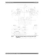
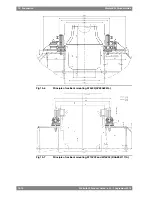
In order to reduce vibrations and structure borne noise, main engines can be resiliently mounted
on rubber elements. The transmission of forces emitted by the engine is 10-20% when using
resilient mounting. For resiliently mounted engines a speed range of 500-750 rpm is generally
available, but cylinder configuration 18V is limited to constant speed operation (750 rpm) and
resilient mounting is not available for 7L32.
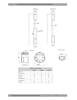
Two different mounting arrangements are applied. Cylinder configurations 6L, 8L, 12V and
16V are mounted on conical rubber mounts, which are similar to the mounts used under
generating sets. The mounts are fastened directly to the engine feet with a hydraulically
tightened bolt. To enable drilling of holes in the foundation after final alignment adjustments
the mount is fastened to an intermediate steel plate, which is fixed to the foundation with one
bolt. The hole in the foundation for this bolt can be drilled through the engine foot. A resin
chock is cast under the intermediate steel plate.
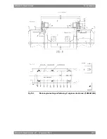
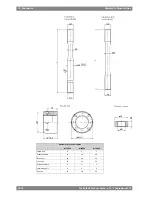
Cylinder configurations 9L and 18V are mounted on cylindrical rubber elements. These rubber
elements are mounted to steel plates in groups, forming eight units. These units, or resilient
elements, each consist of an upper steel plate that is fastened directly to the engine feet,
rubber elements and a lower steel plate that is fastened to the foundation. The holes in the
foundation for the fastening bolts can be drilled through the holes in the engine feet, when the
engine is finally aligned to the reduction gear. The resilient elements are compressed to the
calculated height under load by using M30 bolts through the engine feet and distance pieces
between the two steel plates. Resin chocks are then cast under the resilient elements. Shims
are provided for installation between the engine feet and the resilient elements to facilitate
alignment adjustments in vertical direction. Steel chocks must be used under the side and
end buffers located at each corner if the engine.
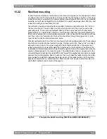
Fig 15-5
Principle of resilient mounting, W6L32 and W8L32 (DAAE048811)
Wärtsilä 32 Product Guide - a21 - 7 September 2016
15-11
15. Foundation
Wärtsilä 32 Product Guide
Summary of Contents for WARTSILA32
Page 18: ...This page intentionally left blank...
Page 72: ...This page intentionally left blank...
Page 130: ...This page intentionally left blank...
Page 150: ...This page intentionally left blank...
Page 186: ...This page intentionally left blank...
Page 204: ...This page intentionally left blank...
Page 210: ...This page intentionally left blank...
Page 216: ...This page intentionally left blank...
Page 238: ...This page intentionally left blank...
Page 246: ...This page intentionally left blank...
Page 248: ...This page intentionally left blank...
Page 251: ......
Page 252: ......
Page 253: ......