


load. Engines with the same speed droop and speed reference will share load equally. Loading
and unloading of a generator is accomplished by adjusting the speed reference of the individual
speed control unit. The speed droop is normally 4%, which means that the difference in
frequency between zero load and maximum load is 4%.
In isochronous mode the speed reference remains constant regardless of load level. Both
isochronous load sharing and traditional speed droop are standard features in the speed
control and either mode can be easily selected. If the ship has several switchboard sections
with tie breakers between the different sections, then the status of each tie breaker is required
for control of the load sharing in isochronous mode.
14.3
Alarm and monitoring signals
Regarding sensors on the engine, please see the internal P&I diagrams in this product guide.
The actual configuration of signals and the alarm levels are found in the project specific
documentation supplied for all contracted projects.
14.4
Electrical consumers
14.4.1
Motor starters and operation of electrically driven pumps
Separators, preheaters, compressors and fuel feed units are normally supplied as
pre-assembled units with the necessary motor starters included. The engine turning device
and various electrically driven pumps require separate motor starters. Motor starters for
electrically driven pumps are to be dimensioned according to the selected pump and electric
motor.
Motor starters are not part of the control system supplied with the engine, but available as
optional delivery items.
14.4.1.1
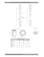
Engine turning device (9N15)
The crankshaft can be slowly rotated with the turning device for maintenance purposes. The
motor starter must be designed for reversible control of the motor. The electric motor ratings
are listed in the table below.
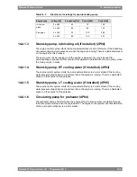
Table 14-2
Electric motor ratings for engine turning device
Current [A]
Power [kW]
Frequency [Hz]
Voltage [V]
Engine type
5.0 / 5.3
2.2 / 2.6
50 / 60
3 x 400 / 440
Wärtsilä 32
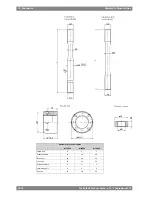
14.4.1.2
Pre-lubricating oil pump
The pre-lubricating oil pump must always be running when the engine is stopped. The pump
shall start when the engine stops, and stop when the engine starts. The engine control system
handles start/stop of the pump automatically via a motor starter.
It is recommended to arrange a back-up power supply from an emergency power source.
Diesel generators serving as the main source of electrical power must be able to resume their
operation in a black out situation by means of stored energy. Depending on system design
and classification regulations, it may be permissible to use the emergency generator.
For dimensioning of the pre-lubricating oil pump starter, the values indicated below can be
used. For different voltages, the values may differ slightly.
14-8
Wärtsilä 32 Product Guide - a21 - 7 September 2016
Wärtsilä 32 Product Guide
14. Automation System
Summary of Contents for WARTSILA32
Page 18: ...This page intentionally left blank...
Page 72: ...This page intentionally left blank...
Page 130: ...This page intentionally left blank...
Page 150: ...This page intentionally left blank...
Page 186: ...This page intentionally left blank...
Page 204: ...This page intentionally left blank...
Page 210: ...This page intentionally left blank...
Page 216: ...This page intentionally left blank...
Page 238: ...This page intentionally left blank...
Page 246: ...This page intentionally left blank...
Page 248: ...This page intentionally left blank...
Page 251: ......
Page 252: ......
Page 253: ......