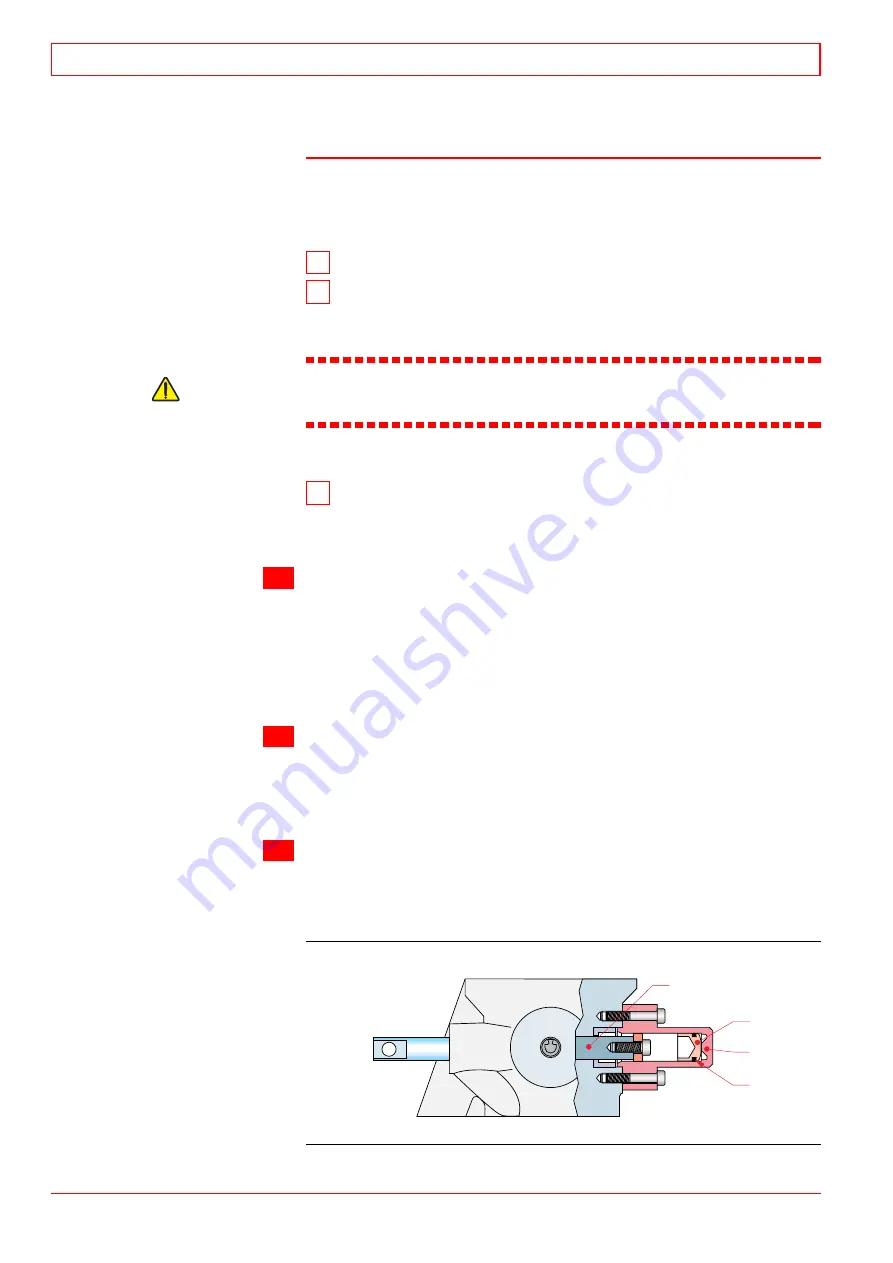
22.3.3 Electro-pneumatic overspeed trip device
22.3.3.1 Maintenance
For maintenance schedule, see chapter 04.
Removal
1 Remove the valve from the injection pump.
2 Remove the piston (2)
by tapping the cylinder (3) against a
piece of wood. If the piston is stuck, press it out by connecting a
grease gun with a suitable adapter to the air supply of the cylinder.
Caution!
If compressed air is used, the piston (2) may be ejected with
such a force that it may cause injuries or damages.
Mounting
3 Ensure that there are no sharp corners or dents
on the
piston (2) or in the cylinder (3). Smoothen if necessary. Apply
a suitable grease and take care not to damage the seal ring
when mounting the piston (2).
a)
Check of stop position
·
Set the stop lever in the work position and the terminal shaft
lever in the max. fuel position.
·
Press the STOP-button on the engine. (Stop sequence is
activated approximately 1 min.)
Note! The starting air
supply should be open.
·
Check that the fuel rack positions is less than 5 mm.
b)
Adjustment of stop position
·
The electro-pneumatic overspeed trip device requires no
adjustment.
·
If a fuel rack position of less than 5 mm cannot be obtained,
check for wear.
c)
Check of tripping speed
·
See section 22.5.3.
Electro-pneumatic overspeed trip device
3
2
1
1. Fuel rack
2. Piston
3. Cylinder
4. Slide ring
4
Fig 22-2
4016049601
22
Control Mechanism
32-200636-01
22 - 4
WÄRTSILÄ 32
Summary of Contents for PAAE051728
Page 4: ......
Page 18: ...Appendix B Welding Precautions 200640 00 6...
Page 26: ...01 Main Data Operating Data and General Design 32 200634 01 01 8 W RTSIL 32...
Page 60: ...Appendix A Environmental Hazards 200507 02A 10...
Page 68: ...Page 7 7 Document No 4V92A0645 Rev j...
Page 84: ...03 Start Stop and Operation 32 200402 04 03 12 W RTSIL 32...
Page 98: ...04 Maintenance Schedule 32 200623 01 04 14 W RTSIL 32...
Page 154: ...07 Tightening Torques and Use of Hydraulic Tools 32 200643 01 07 30 W RTSIL 32...
Page 162: ...08 Operating Troubles Emergency Operation 32 200402 01 08 8 W RTSIL 32...
Page 164: ...Specific Installation Data 2005 01 09 2...
Page 178: ...10 Engine Block with Bearings Oil Sump and Cylinder Liner 32 200150 10 14 W RTSIL 32 34SG...
Page 216: ...Appendix A Testing of cylinder tightness 32 200142 A 4 W rtsil 20 32 34...
Page 226: ...13 Camshaft Driving Gear 32 200546 02 13 10 W RTSIL 32...
Page 254: ...15 Turbocharging and Air Cooling 32 200549 10 15 20 W RTSIL 32...
Page 274: ...16 Injection System 32 200627 01 16 20 W RTSIL 32...
Page 280: ...Fuel System 32 200508 07 17 6 W RTSIL 32...
Page 314: ...19 Cooling Water System 32 200050 19 14 W RTSIL 32...
Page 394: ...23 Instrumentation and Automation 32 200115 II 23 60 W RTSIL 32...


