background image

wc_tx004062gb_FM10.fm

27

Rammer

Operation

2.6

Low Oil Shut-Off Switch—WM100

Overview

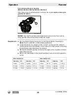
The low oil shutoff switch is designed to prevent engine damage caused by an 
insufficient amount of oil. When the engine is started, an illuminated indicator

 (a)


notifies the operator of the status of the engine oil level.


wc_gr011597

a

Condition

Engine oil level status

Required action

Indicator flashes 
quickly once upon 
engine startup

Engine oil level is 
acceptable.

None.

Indicator flashes 
slowly

Engine starts, but 
stops after 10–15 sec-
onds

Engine oil level is low.

Add engine oil. See 
chapter 

Technical Data 

for quantity and type.

Indicator illuminates 
and remains lit

Engine starts and 
continues to run

Engine oil level is 
acceptable, but low oil 
shutoff switch is not 
functioning properly.

Check connections on 
low oil shutoff switch. 
Replace the switch if 
indicator remains lit.

Indicator does not 
flash upon engine 
startup

Engine starts and 
continues to run

Low oil shutoff switch is 
not functioning properly.

Check connections on 
low oil shutoff switch. 
Replace the switch if 
indicator still does not 
illuminate.

Summary of Contents for BS 50-4s, BS 50-4As

Page 1: ...Repair Manual Vibratory Rammer 5100018465 01 1015 5 1 0 0 0 1 8 4 6 5 EN...

Page 2: ...on from Wacker Neuson Production Americas LLC Any type of reproduction or distribution not authorized by Wacker Neuson Production Americas LLC represents an infringement of valid copyrights Violators...

Page 3: ...chine Item Number BS 50 4s BS 50 4As 5200000644 5200000662 5200000679 5200000680 5200018226 5200018219 5100015099 BS 60 4s BS 60 4As 5200000647 5200000648 5200000667 5200000668 5200000674 5200000675 5...

Page 4: ...in this manual refer to Wacker Neuson factory installed components Your machine may vary depending on the requirements of your specific region CALIFORNIA Proposition 65 Warning Combustion exhaust som...

Page 5: ...e following consequences Serious injury hazards to the operator and persons in the work area Permanent damage to the machine which will not be covered under warranty Contact your Wacker Neuson dealer...

Page 6: ...wc_tx004061gb_FM10 fm 6 Rammer Foreword...

Page 7: ...topping the Machine 25 2 6 Low Oil Shut Off Switch WM100 27 2 7 Low Oil Shut Off Switch Honda 28 3 Troubleshooting 29 3 1 Diagnosing Starting Issues 29 3 2 Diagnosing Performance Issues 30 3 3 Checkin...

Page 8: ...retor Honda 94 4 24 Installing the Carburetor Honda 98 4 25 Removing the Engine WM 80 101 4 26 Installing the Engine WM 80 105 4 27 Removing the Engine Honda 109 4 28 Installing the Engine Honda 112 4...

Page 9: ...Data 181 6 1 BS 50 2i 181 6 2 BS 50 2i Operating Weight 181 6 3 BS 60 2i 182 6 4 BS 60 2i Operating Weight 182 6 5 BS 70 2i 183 6 6 BS 70 2i Operating Weight 183 6 7 BS 50 2 184 6 8 BS 50 2 Operating...

Page 10: ...Table of Contents Rammer wc_br5100018465_FM10TOC fm 10...

Page 11: ...ntial personal hazards Obey all safety messages that follow this symbol DANGER DANGER indicates a hazardous situation which if not avoided will result in death or serious injury To avoid death or seri...

Page 12: ...e as a ladder support or work surface Using the machine to carry or transport passengers or equipment Using the machine as a hammer or for other demolition work Attaching the machine to any other mach...

Page 13: ...gs Application area Be aware of the application area Keep unauthorized personnel children and pets away from the machine Remain aware of changing positions and the movement of other equipment and pers...

Page 14: ...do not hinder movement Safety glasses with side shields Hearing protection Safety toed footwear After Use Stop the engine when the machine is not being operated Close the fuel valve on engines equippe...

Page 15: ...en servicing or maintaining the machine Read and understand the service procedures before performing any service to the machine All adjustments and repairs must be completed before operating the machi...

Page 16: ...pes of fuels or flammable solvents to clean the machine Fumes from fuels and solvents can become explosive Personal Protective Equipment PPE Wear the following Personal Protective Equipment PPE while...

Page 17: ...When refueling the engine Clean up any spilled fuel immediately Refill the fuel tank in a well ventilated area Re install the fuel tank cap after refueling Do not smoke Do not refuel a hot or running...

Page 18: ...se an oxygenated fuel be sure it is unleaded and meets the minimum octane rating requirement Before using an oxygenated fuel confirm the fuel s contents Some states and provinces require this informat...

Page 19: ...nated fuel be sure it is unleaded and meets the minimum octane rating requirement Before using an oxygenated fuel confirm the fuel s contents Some states and provinces require this information to be p...

Page 20: ...e oil ratio in a range from 50 1 to 100 1 can be used For optimum engine performance and durability a 100 1 ratio with a fully synthetic oil meeting the specification described above is preferred Mix...

Page 21: ...or until you see fuel in the bulb Note The engine will not become flooded by pumping the purge bulb more than 10 times Pumping the purge bulb removes air from the fuel system It does not pump fuel int...

Page 22: ...such a way that you are not squeezed between the rammer and solid objects Make sure you have solid footing when operating the rammer on uneven ground or when compacting coarse material Stopping the m...

Page 23: ...or until you see fuel in the bulb Note The engine will not become flooded by pumping the purge bulb more than 10 times Pumping the purge bulb removes air from the fuel system It does not pump fuel int...

Page 24: ...such a way that you are not squeezed between the rammer and solid objects Make sure you have solid footing when operating the rammer on uneven ground or when compacting coarse material Stopping the m...

Page 25: ...until you see fuel in the bulb Note The engine will not become flooded by pumping the purge bulb more than 10 times Pumping the purge bulb removes air from the fuel system It does not pump fuel into t...

Page 26: ...l Guide the rammer in such a way that you are not squeezed between the rammer and solid objects Make sure you have solid footing when operating the rammer on uneven ground or when compacting coarse ma...

Page 27: ...le None Indicator flashes slowly Engine starts but stops after 10 15 sec onds Engine oil level is low Add engine oil See chapter Technical Data for quantity and type Indicator illuminates and remains...

Page 28: ...l When starting the engine an illuminated indicator a notifies the operator that the engine oil level is low wc_gr011882 a Condition Engine oil level status Required action Indicator does not flash an...

Page 29: ...tion wiring Checking the Ignition Wiring 3 7 Engine starts but does not come up to full speed See topics No 1 Check the fuel flow Checking the Fuel Flow 3 3 2 Check the fuel cap 3 Check carburetor for...

Page 30: ...performance problems are Engine runs but carburetor floods See topics No 1 Check carburetor for dirt See engine repair manual 2 Check the fuel flow Checking the Fuel Flow 3 3 Probable cause See Topic...

Page 31: ...gh the fuel hoses Is there fuel flow in the fuel hoses 3 Locate the in line fuel filter a 4 Cut the fuel hose b as close to the nipple as possible This procedure continues on the next page WARNING Fir...

Page 32: ...ve the in tank fuel filter See topic Removing the Fuel Tank 8 Clean or replace the in tank fuel filter Result The fuel flow has now been checked Yes ____ No ____ Replace the in line fuel filter Remove...

Page 33: ...to 4 2 mm 0 166 in 2 Attach the end of the ignition cable to one end of the tester 3 Ground the other end of the tester by clipping it onto the engine cylinder 4 Crank the engine using the rewind sta...

Page 34: ...a normally open NO switch when activated placed in the STOP position it creates a short circuit to ground The short circuit prevents the spark plug from firing and stops the engine Procedure Perform t...

Page 35: ...engines check for continuity between the wire the engine housing On 2 stroke engines check for continuity across the connector Is there continuity Result The throttle stop switch has now been checked...

Page 36: ...pe 3 Connect the leak down tester b to the engine at the spark plug hole 4 Set the regulator of the air supply to 100 psi Test the engine leak down using the instruction of the leak down tester Does t...

Page 37: ...re Perform the procedure below to remove check the ignition wiring 1 Remove the housing cover a from the WM 80 engine 2 Remove the nut b and the washer c 3 Using puller 5000046503 d pull the flywheel...

Page 38: ...rocedure below to check engine combustion 1 Remove the spark plug a 2 Install the compression gauge b into the cylinder 3 Pull the starter rope several times and measure the pressure on the gauge Is 6...

Page 39: ...level in the fuel tank Fill the fuel tank if necessary 2 Check the purge bulb a If there is no fuel in the purge bulb a vapor lock condition may exist 3 Check for air bubbles in the return fuel hose...

Page 40: ...illed Fresh oil as specified in Technical Data Phillips screwdriver Plastic syringe Clean dry absorbent cloth or paper towels Purging the oil supply line Perform the procedure below to purge the oil s...

Page 41: ...the following method Disconnect the oil discharge line at the oil pump d Using a plastic syringe e filled with oil inject oil into the oil discharge line until the air bubbles are gone and oil is visi...

Page 42: ...aintained at the correct level to ensure the ramming system operates efficiently Procedure Perform the procedure below to drain the ramming system oil 1 Remove the sight glass a 2 Tilt the rammer back...

Page 43: ...to refill the ramming system oil NOTICE Do not overfill the ramming system with oil High levels of oil can create a hydraulic lock in the ramming system This can result in erratic operation and cause...

Page 44: ...l 6 Oil is at the correct level when the oil fills 1 2 to 3 4 of the sight glass a 7 Once the correct oil level is achieved tip the rammer forward and secure the rammer 8 Remove the sight glass clean...

Page 45: ...amming system operates efficiently Procedure Perform the procedure below to drain the ramming system oil 1 Tilt the rammer backward until it is resting on the handle 2 Place a suitable container under...

Page 46: ...low to refill the ramming system oil NOTICE Do not overfill the ramming system with oil High levels of oil can create a hydraulic lock in the ramming system This can result in erratic operation and ca...

Page 47: ...l level The oil is at the correct level when the oil fills 1 2 to 3 4 of the sight glass 6 Once the correct oil level is achieved tip the rammer forward and secure the rammer 7 Remove the sight glass...

Page 48: ...a vertical position 2 Remove the six nuts a and the lock washers b 3 Remove the lifting handle c and the two spacers d This procedure continues on the next page To view an animation of this procedure...

Page 49: ...Raise the machine off the shoe g and secure it in position 5 Remove the three rear plow bolts e and the three front plow bolts f Note To prevent the plow bolts from spinning press the plow bolt heads...

Page 50: ...ottom plate while installing the nuts 1 Raise the machine off the ground Install the shoe g to the machine using three plow bolts e three plow bolts f two spacers d the lifting handle c six washers b...

Page 51: ..._tx004029gb_FM10 fm 51 Rammer Disassembly and Reassembly Continued from the previous page 2 Lower the machine to the ground and remove the lifting devices Results The ramming shoe has now been install...

Page 52: ...on 2 Remove the six lock nuts a the lock washers b and the lifting handle c 3 Raise the machine off the shoe d Position the machine in a secure place This procedure continues on the next page WARNING...

Page 53: ...Note Note the size and location of the plow bolts e f and g to aid during installation 4 Remove the six plow bolts e f and g Note To prevent the plow bolts from spinning press the plow bolt heads fir...

Page 54: ...olts e the two plow bolts f the two plow bolts g lifting handle c six lock washers b and the six lock nuts a Note To prevent the plow bolts from spinning press the plow bolt heads firmly into the bott...

Page 55: ..._tx004029gb_FM10 fm 55 Rammer Disassembly and Reassembly Continued from the previous page 2 Lower the machine to the ground and remove the lifting devices Result The ramming shoe has now been installe...

Page 56: ...the lifting cable 1 Remove the four socket head screws b and the two nuts c 2 Remove the brace d and the lifting cable a Result The lifting cable has now been removed To view an animation of this proc...

Page 57: ...he four socket head screws b Set the brace d and the lifting cable a into position and fasten the lifting cable using the four socket head screws b and the two nuts c Torque the screws to 41 Nm 30 ft...

Page 58: ...cedure Perform the procedure below to remove the oil tank 1 Remove the fuel tank See topic Removing the Fuel Tank 2 Remove the four screws and washers a that hold the oil tank b to the machine This pr...

Page 59: ...page 3 Remove the hose and wire from the clamp c 4 Lift the oil tank up from the machine open the oil tank cap and drain the oil into an approved container 5 Hold the oil filter d and unscrew the oil...

Page 60: ...low to install the oil tank 1 Hold the oil filter d and screw the oil tank b onto the oil filter 2 Set the oil tank on the machine and install the hose and the wire in the clamp c This procedure conti...

Page 61: ...pply Loctite 243 to the four screws a and fasten the oil tank b to the machine with the four screws and washers Torque the four screws to 9 4 Nm 6 9 ft lbs 4 Fill the oil tank with oil 5 Install the f...

Page 62: ...mental regulations 2 Disconnect the clamp a and pull the fuel hose b from the fuel tank 3 Disconnect the clamp d at the fuel filter c 4 Hold the fuel hose e near the fuel filter and unscrew the fuel f...

Page 63: ...ious page 5 Remove and retain the clamp f for reuse during installation of the fuel tank Note Graphic is representative only your machine may vary 6 Remove the six screws j and lift the fuel tank g fr...

Page 64: ...e fuel tank to the guide handle Torque the six screws to 9 4 Nm 6 9 ft lbs Note Graphic is representative only your machine may vary This procedure continues on the next page WARNING Fuel is flammable...

Page 65: ...the end of the fuel hose e near the fuel filter c and screw the fuel filter to the fuel tank 5 Install the clamp d at the fuel filter c 6 Remove 10 mm 3 8 in off the end of the hose b Connect the fue...

Page 66: ...ental regulations 2 Remove the four screws a and washers that fasten the ramming system to the crankcase 3 With the aid of an assistant roll the crankcase and place a wood block b between the crankcas...

Page 67: ...he crankcase from the ramming system 7 Remove the O ring f from the ramming system Note Do not reuse the O ring 8 Loosen the upper clamp h 9 Stand on the ramming shoe and pull the guide cylinder e fro...

Page 68: ...oth ends This procedure continues on the next page CAUTION Pinch point hazard Hands and or fingers may become pinched between the cylinder guide and the bellows during installation Keep hands open wit...

Page 69: ...Set the bellows d on the protective pipe f as square as possible 5 Set the upper clamp c in place 6 Set the cylinder guide a onto the bellows as square as possible 7 With a strong push slam the cylind...

Page 70: ...rod q with the ram j 13 Install the piston pin n and new end plugs m Note Use new end plugs m whenever the piston pin n has been removed 14 Remove the two wood blocks 15 Apply Loctite 243 to the four...

Page 71: ...c so the adjustment screw is 90 from the sight glass p 19 Position the lower clamp e so the adjustment screw is 90 from the sight glass p 20 Torque the upper and lower clamps to 13 5 Nm 10 ft lbs 21 F...

Page 72: ...egulations 2 Remove the three screws b and the carburetor guard a 3 Loosen screw g and remove the throttle cable c 4 Loosen clamp e and remove the air tube d 5 Remove the spark plug wire f from the re...

Page 73: ...e carburetor fittings and drain the fuel into an approved container 7 Clamp if necessary then cut the fuel hose k close to the carburetor fittings and drain the fuel into an approved container 8 On ma...

Page 74: ...bly Continued from the previous page 11 Remove two screws q and two washers r to disassemble the air tube adapter s upper gasket t carburetor u lower gasket v and the carburetor adapter w This procedu...

Page 75: ...wc_tx004029gb_FM10 fm 75 Rammer Disassembly and Reassembly Continued from the previous page 12 Disassemble the carburetor as needed Result The carburetor has now been removed wc_gr012678...

Page 76: ...e carburetor 1 Assemble the carburetor as needed This procedure continues on the next page WARNING Fuel is flammable and may ignite Keep all sources of ignition far away while performing this procedur...

Page 77: ...ws q and washers r Torque screws to 5 Nm 4 ft lbs 3 Install the two washers n and two nuts o fastening the adapter gasket p and the carburetor assembly m to the machine Torque to 10 8 Nm 8 ft lbs 4 Co...

Page 78: ...apter and tighten clamp e 7 Install the throttle cable c and tighten the screw g 8 Install the spark plug wire f into the retainer clip 9 Apply Loctite 243 to the three screws b and fasten the carbure...

Page 79: ...regulations 2 Remove the three screws b and the carburetor guard a 3 Loosen screw g and remove the throttle cable c 4 Loosen clamp e and remove the air tube d 5 Remove the spark plug wire f from the...

Page 80: ...e from the fitting 6 Clamp if necessary then cut the fuel filter hose h close to carburetor fitting and drain the fuel into an approved container 7 Clamp if necessary then cut the fuel hose k close to...

Page 81: ...bly Continued from the previous page 10 Remove two screws p and two washers q to disassemble the air tube adapter r upper gasket s carburetor t lower gasket u and the carburetor adapter v This procedu...

Page 82: ...wc_tx004029gb_FM10 fm 82 Rammer Disassembly and Reassembly Continued from the previous page 11 Disassemble the carburetor as needed Result The carburetor has now been removed wc_gr012679...

Page 83: ...the carburetor 1 Assemble the carburetor as needed This procedure continues on the next page WARNING Fuel is flammable and may ignite Keep all sources of ignition far away while performing this proced...

Page 84: ...he carburetor adapter v with screws p and washers q Torque screws to 5 Nm 4 ft lbs 3 Install two washers m and two nuts n fastening the adapter gasket o and the carburetor assembly j to the machine To...

Page 85: ...g wire f in the retainer clip 6 Connect the air tube d and tighten the clamp e 7 Install the throttle cable c and tighten the screw g 8 Apply Loctite 243 to the three screws b and install the carburet...

Page 86: ...ents into an approved container Note Dispose of fuel in accordance with local environmental regulations 2 Remove the four screws h and swing the carburetor guard a to the side 3 Loosen the clamp g and...

Page 87: ...as possible Carefully cut the remaining hose from the fitting 4 Clamp if necessary then cut the fuel filter hose j close to the carburetor fitting and drain the fuel into an approved container 5 Clamp...

Page 88: ...overnor linkage x and the spring y connecting the governor w to the carburetor assembly 9 Remove two nuts o and remove the air intake p the two gaskets u and the carburetor v 10 Remove the two screws...

Page 89: ...wc_tx004029gb_FM10 fm 89 Rammer Disassembly and Reassembly Continued from the previous page 11 Disassemble the carburetor as needed Result The carburetor has now been removed wc_gr012675...

Page 90: ...rench Loctite 243 Procedure Perform the procedure below to install the carburetor 1 Assemble the carburetor as needed This procedure continues on the next page WARNING Fuel is flammable and may ignite...

Page 91: ...the carburetor adapter s to the engine 4 Install the two gaskets u the carburetor v and the air intake p to the carburetor adapter s Fasten using two nuts o 5 Install the governor linkage x and sprin...

Page 92: ...m 92 Rammer Disassembly and Reassembly Continued from the previous page 7 Connect the vent hose k fuel filter hose j and fuel hose e to the carburetor fittings This procedure continues on the next pag...

Page 93: ...previous page 8 Connect the air tube f to the air intake and tighten the clamp g 9 Apply Loctite 243 to the four screws h and fasten the carburetor guard a to the machine Torque the screws to 25 Nm 1...

Page 94: ...dance with local environmental regulations 2 Remove any wire ties attached to the carburetor guard b 3 Remove the screw a and the nut fastening the fuel filter and the clip to the carburetor guard b 4...

Page 95: ...ly cut the remaining hose from the fitting 6 Clamp if necessary then cut the fuel filter hose m close to carburetor fitting and drain the fuel into an approved container 7 Clamp if necessary then cut...

Page 96: ...96 Rammer Disassembly and Reassembly Continued from the previous page 10 Remove the governor rod f and the spring g connecting the governor arm to the carburetor This procedure continues on the next...

Page 97: ...om the two stud bolts o 12 Remove the elbow p the gasket r and the carburetor q from the two stud bolts o 13 Remove five gaskets s t u w and y one plate v and one insulator x from the two stud bolts o...

Page 98: ...q as needed 2 Install the five gaskets s t u w and y one plate v and one insulator x to the two stud bolts o 3 Install the carburetor q the gasket r and the elbow p to the two stud bolts o 4 Fasten u...

Page 99: ...99 Rammer Disassembly and Reassembly Continued from the previous page 5 Install the governor rod f and the spring g connecting the governor arm to the carburetor This procedure continues on the next...

Page 100: ...ube d and tighten the hose clamp e 9 Apply Loctite 243 to the four screws c and fasten the carburetor guard b to the machine Torque the screws to 25 Nm 18 ft lbs 10 Apply Loctite 243 to the screw a an...

Page 101: ...o remove the WM 80 engine 1 Remove the carburetor See topic Removing the Carburetor WM80 oil injected or Removing the Carburetor WM80 non oil injected 2 Remove the screws a and b This procedure contin...

Page 102: ...wc_tx004029gb_FM10 fm 102 Rammer Disassembly and Reassembly Continued from the previous page 3 Remove the screw c and the muffler assembly d This procedure continues on the next page wc_gr012879 c d...

Page 103: ...ly and Reassembly Continued from the previous page 4 Remove the two screws e and the bracket f 5 Disconnect the stop switch connector g and the float switch connector h if equipped This procedure cont...

Page 104: ...x004029gb_FM10 fm 104 Rammer Disassembly and Reassembly Continued from the previous page 6 Remove the screws j on each side and remove the engine k t Result The engine has now been removed wc_gr012881...

Page 105: ...edure below to install the engine 1 Apply Loctite 243 to the four screws j and fasten the engine k to the machine Torque the screws to 27 Nm 20 ft lbs This procedure continues on the next page To view...

Page 106: ...the previous page 2 Apply Loctite 243 to the screws e and fasten the bracket f to the machine Torque the screws to 24 Nm 18 ft lbs 3 Connect the stop switch connector g and the float switch connector...

Page 107: ...us page 4 Hold the muffler flush to the bottom of the engine Apply Loctite 243 to the screw a Install and torque the screw to 18 Nm 13 ft lbs 5 Apply Loctite 243 to the screw b Install and torque the...

Page 108: ...vious page 6 Apply Loctite 243 to the screw c Install and torque the screw to 24 Nm 18 ft lbs 7 Install the carburetor See topic Installing the Carburetor WM80 oil injected or Installing the Carbureto...

Page 109: ...ocedure Perform the procedure below to remove the GX100 Honda engine 1 Remove the carburetor See topic Removing the Carburetor Honda 2 Loosen the screw b and the nut c and remove the throttle cable d...

Page 110: ...FM10 fm 110 Rammer Disassembly and Reassembly Continued from the previous page 4 Remove the screw g and the wire f from the engine 5 Disconnect the wire h This procedure continues on the next page wc_...

Page 111: ...q and remove the low oil shutdown switch from the lower engine guard o 8 Remove the four 20 mm screws n and the two 30 mm m screws and remove the lower engine guard o from the machine 9 With the aid...

Page 112: ...ts e Tighten the nuts e but do not torque the nuts at this time 2 Apply Loctite 243 to the two 30 mm screws m and the four 20 mm screws n 3 Fasten the lower engine guard o to the machine with the scre...

Page 113: ...b_FM10 fm 113 Rammer Disassembly and Reassembly Continued from the previous page 6 Fasten the wire f to the engine with the screw g 7 Connect the wire h This procedure continues on the next page wc_gr...

Page 114: ...and screw b 9 Apply Loctite 243 to the two engine mounting nuts e and the two engine mounting nuts on the opposite side of the machine Torque all four engine mounting nuts to 25 Nm 18 ft lbs 10 Insta...

Page 115: ...Requirements Machine shut down and cool Procedure Perform the procedure below to remove the Robin engine 1 Disconnect the wire b and remove the screw c 2 Remove the wires b and d from the grommet on t...

Page 116: ...rom the previous page 3 Remove the carburetor guard a 4 Remove the low oil shutdown switch e from the lower guard f 5 Remove the lower guard f 6 Remove the two nuts h and the support bracket g This pr...

Page 117: ...ve the air intake tube j 8 Label the fuel hoses to aid in re installation 9 Clamp if necessary then cut the fuel filter hose k fuel hose m and the vent hose l close to the carburetor fittings and drai...

Page 118: ...8 Rammer Disassembly and Reassembly Continued from the previous page 10 Disconnect the throttle cable n 11 Remove the two nuts p the heat shield q and the engine r t Result The engine has now been rem...

Page 119: ...Torque wrench Loctite 243 Procedure Perform the procedure below to install the WM 100 engine 1 Install the engine r the heat shield q and two engine mounting nuts p Do not tighten nuts p at this time...

Page 120: ...all the lower guard f the low oil shutdown switch e and the support bracket g 5 Apply Loctite 243 to the two engine mounting nuts h and the two engine mounting nuts on the opposite side of the machine...

Page 121: ...buretor guard a to the machine Torque the screws to 25 Nm 18 ft lbs 8 Install the wire d through the rubber grommet on the carburetor guard and fasten to the engine shroud with the screw c 9 Install t...

Page 122: ...that fasten the ramming system to the crankcase 3 With the aid of an assistant roll the crankcase and place a wood block b between the crankcase and the ramming system 4 With the aid of an assistant r...

Page 123: ...and the piston pin f that holds the connecting rod to the ram c Note Do not reuse the end plugs 6 With the aid of an assistant lift and remove the crankcase from the ramming system 7 Remove O ring g...

Page 124: ...nder 3 With the aid of an assistant position the upper machinery on the two wood blocks and align the crankcase connecting rod h with the ram c Note Use new end plugs e whenever the piston pin f has b...

Page 125: ...octite 243 to the four screws a Note When reusing bolts clean the threads thoroughly before use 7 Fasten the upper machinery to the ramming system with four screws a and washers Torque the four screws...

Page 126: ...orm the procedure below to remove the crankcase 1 Remove the upper machinery See topic Removing the Upper Machinery 2 Remove the engine See topic Removing the Engine 3 Remove the clutch drum See topic...

Page 127: ...0 fm 127 Rammer Disassembly and Reassembly Continued from the previous page 5 Remove the six screws f and remove the guide handle assembly g from the crankcase This procedure continues on the next pag...

Page 128: ...ding the bearing k to the crank gear 9 Pull the bearing free of the shaft using the split puller s and a 2 jaw bearing puller t 10 Remove the small retaining ring u that holds the connecting rod and t...

Page 129: ...ange surface 2 Place the large retaining ring m over the shaft of the crank gear c 3 Press the ball bearing k onto the shaft of the crank gear and re install the small retaining ring j 4 Press the bal...

Page 130: ...the slotted hole q in the crank gear and seat the large retaining ring m in the groove 8 Install a new O ring e 9 Re install the clutch drum See topic Installing the Clutch Drum Note The following st...

Page 131: ...uide handle assembly g to the crankcase using six screws f Apply Loctite 243 and torque the screws to 31 Nm 23 ft lbs 12 Re install the engine See topic Installing the Engine 13 Re install the upper m...

Page 132: ...vary 3 Prevent the clutch d from turning and loosen the clutch nut b Note Loosen the nut but do not completely remove it from the engine crankshaft This will protect the crankshaft threads from the cl...

Page 133: ...r in the clutch hub and the engine crankshaft are absolutely free of oil or grease 2 Install washer b and nut a Torque the nut to 34 Nm 23 ft lbs Note Graphic is representative only your machine may v...

Page 134: ...g the Engine Note The front cover cannot be removed until the connecting rod is disconnected from the ram 3 Remove the four screws g from the front cover 4 Insert a screwdriver into the slots on each...

Page 135: ...om the previous page 5 Remove the small retaining ring k from the clutch drum shaft m 6 Press the clutch drum shaft m from the crankcase Inspect the clutch drum shaft for wear or damage and replace it...

Page 136: ...m bearing q from the crankcase Inspect the clutch drum bearing for wear or damage and replace it if necessary 9 The needle bearing r remains intact in the crankcase cover Inspect the needle bearing fo...

Page 137: ...ocedure below to install the clutch drum 1 If the needle bearing r was removed press a new needle bearing into the front cover h until seated in the bore s Note Keep the inside of the clutch drum abso...

Page 138: ...clutch drum bearing q into the crankcase and secure the clutch drum bearing with the retaining ring p 3 Pack the shaft seal n with grease Install the shaft seal with the open side facing the bearing q...

Page 139: ...l retaining ring k 6 Install the front cover h to the crankcase Apply Loctite 243 and torque screws g to 49 Nm 36 ft lbs 7 Install upper machinery See topic Installing the Upper Machinery 8 Install th...

Page 140: ...ump Requirements Machine shut down and cool Engine removed Oil tank at least 1 4 full Procedure Perform the procedure below to remove and test the oil pump 1 Remove the engine See topic Removing the E...

Page 141: ...until oil flows from the output nipple f then close the bleed screw 7 Rotate the small gear h within the pump Oil should flow out of the output nipple f within 20 revolutions of the small gear If no...

Page 142: ...mmer Disassembly and Reassembly Continued from the previous page 8 Remove the cartridge assembly j O ring k and gasket m Inspect parts for damage Replace if necessary t Result The oil pump has now bee...

Page 143: ...yringe Procedure Perform the procedure below to install the oil pump 1 Install the O ring k cartridge assembly j and gasket m This procedure continues on the next page To view an animation of this pro...

Page 144: ...her end into a source of 2 cycle engine oil p Then draw the oil from the source into the output oil hose Fill the output oil hose with oil 4 Connect the output hose b using the clamp a Connect the oth...

Page 145: ...the procedure below to remove the spring system cover 1 Remove the bellows See topic Removing the Bellows 2 Remove the ramming shoe See topic Removing the Ramming Shoe BS50 or Removing the Ramming Sho...

Page 146: ...g system cover and into the spring cylinder 5 Place the spring cylinder in a hydraulic press and position the head of the press ram in firm contact with the center of the spring system cover b 6 Lock...

Page 147: ...sembly Continued from the previous page 9 After all the spring pressure is released remove the three M8 x 206 mm guide screws x spring system cover b gasket d and lower spring set c Result The spring...

Page 148: ...the hydraulic press method may be used Procedure Perform the procedure below to install the spring system cover This procedure continues on the next page WARNING Personal injury hazard The spring syst...

Page 149: ...previous page 1 Install the lower spring set c new gasket d and spring system cover b into the spring cylinder 2 Install three M8 x 206 mm guide screws x through the spring system cover and into the...

Page 150: ...y Loctite 243 and install the two screws a that hold the spring system cover b to the spring cylinder Torque the two screws to 24 Nm 18 ft lbs 7 Remove the three M8 x 206 mm guide screws x 8 Apply Loc...

Page 151: ...emove the spring system cover Spring Box Tool Method 1 Remove the bellows See topic Removing the Bellows 2 Remove the ramming shoe See topic Removing the Ramming Shoe BS50 or Removing the Ramming Shoe...

Page 152: ...Note Spring box tool P N 5000081423 This procedure continues on the next page 4 3 1 5 3 2 4 5 1 3 4 5 2 3 3 3 5 St Maschine Qt Cont M quina Machine Qty Machine Schraube position La posicion del torni...

Page 153: ...stem cover 4 Remove the three screws b 5 Insert the three spring box screws c through the three selected holes in the spring box tool and turn the screws into the spring cylinder until they bottom out...

Page 154: ...m the spring system cover 8 Slowly loosen the threaded rod d until the springs have fully expanded and the pressure is released 9 After all the spring pressure is released remove the spring box screws...

Page 155: ...aulic press method used Procedure Perform the procedure below to install the spring system cover This procedure continues on the next page WARNING Personal injury hazard The spring system cover is und...

Page 156: ...Tool Method Note Spring box tool P N 5000081423 This procedure continues on the next page 4 3 1 5 3 2 4 5 1 3 4 5 2 3 3 3 5 St Maschine Qt Cont M quina Machine Qty Machine Schraube position La posicio...

Page 157: ...selected holes in the spring box tool and through the holes in the spring system cover 5 Turn the spring box screws c into the spring cylinder until they bottom out 6 Turn the threaded rod d until the...

Page 158: ...the remaining three screws b that hold the spring system cover to the spring cylinder Torque the screws to 24 Nm 18 ft lbs 11 Install the ramming shoe See topic Installing the Ramming Shoe BS50 or Ins...

Page 159: ...e yoke c to set on the flange surface of the rammer and the jaws to reach the bottom of the impact bushing 2 Push the jaws a of the impact bushing puller over the impact bushing b until it seats at th...

Page 160: ...ing b and discard the impact bushing 5 Place a drift pin through the holes on the end of the ram e to prevent the ram from turning 6 Use an impact wrench to remove the locknut k 7 Remove the piston gu...

Page 161: ...through the holes on the end of the ram e to prevent the ram from turning 5 Apply Loctite 243 to the locknut k then re install it Torque the locknut to BS50 2i 176 Nm 130 ft lbs BS60 2 BS60 4 BS60 4A...

Page 162: ...ssembly and Reassembly Continued from the previous page 7 Using one of the two recommended methods re install the lower springs and the spring system cover 8 Re install the ramming shoe Result The upp...

Page 163: ...shuts off by itself within approximately 25 seconds even with oil in the oil tank the float switch could be faulty Requirements Machine shut down and cool Multimeter Oil tank at least 1 4 full Torque...

Page 164: ...onnector c 3 Check the continuity of the float switch by measuring across the connector terminals x Does the float switch have continuity This procedure continues on the next page Yes ____ No ____ The...

Page 165: ...ly Continued from the previous page 4 Reconnect the float switch 5 Apply Loctite 243 to the three screws b and fasten the carburetor guard a to the machine Torque the screws to 23 Nm 17 ft lbs t Resul...

Page 166: ...place the float switch Note Dispose of oil in accordance with local environmental regulations 1 Set the machine on a plastic sheet and drain the oil tank contents into an approved container 2 Remove t...

Page 167: ...the stop switch e and the float switch f Note For ease of installation record the routing of the float switch wire 4 Remove the screw c and the clamp d 5 Remove the oil hose h and the float switch wi...

Page 168: ...Cut the oil hose h from the float switch m Remove and retain the clamp k for re use during installation 7 Using two flathead screwdrivers one on either side of the float switch m pry the float switch...

Page 169: ...ute and connect the float switch connector f and re connect the stop switch connector e 2 Install the clamp d and the screw c 3 Before installing the new float switch m apply oil to the shaft p 4 Move...

Page 170: ...3 8 in 10 mm off the end of the oil hose h 6 Insert the float switch m into the oil filter n 7 Install the clamp k and connect the oil hose h to the float switch m 8 Install the oil hose and the wire...

Page 171: ...ly and Reassembly Continued from the previous page 9 Apply Loctite 243 to the three screws b and fasten the carburetor guard a to the machine Torque the screws to 23 Nm 17 ft lbs Result The float swit...

Page 172: ...0 Engine speed idle rpm 2 000 100 Clutch Engagement rpm 2 650 100 Max rated power rated speed1 kW hp 2 4 3 2 Spark plug type NGK BMR4A or CHAMPION RCJ14 Electrode gap mm in 0 6 0 7 0 023 0 027 Air cle...

Page 173: ...idle rpm 1 850 150 Clutch Engagement rpm 2 650 100 Max rated power rated speed1 kW hp 2 35 3 15 2 80 3 75 Spark plug type NGK CR5HSB or DENSO U16FSR UB Electrode gap mm in 0 6 0 7 0 024 0 028 Air cle...

Page 174: ...4 200 100 Engine speed idle rpm 2 000 100 Clutch Engagement rpm 2 650 100 Max rated power rated speed1 kW hp 2 4 3 2 Spark plug type NGK BMR4A or CHAMPION RCJ14 Electrode gap mm in 0 6 0 7 0 023 0 02...

Page 175: ...ngine speed idle rpm 1 850 150 Clutch Engagement rpm 2 650 100 Max rated power rated speed1 kW hp 2 35 3 15 2 80 3 75 Spark plug type NGK CR5HSB or DENSO U16FSR UB Electrode gap mm in 0 6 0 7 0 024 0...

Page 176: ...1 850 150 Clutch Engagement rpm 2 650 100 Max rated power rated speed1 kW hp 2 80 3 75 Spark plug type NGK CR5HSB or DENSO U16FSR UB Electrode gap mm in 0 6 0 7 0 024 0 028 Air cleaner type Four stag...

Page 177: ...nment by Equipment for use outdoors Machine Sound Pressure at Operator s Location dB A Guaranteed Sound Power dB A BS 50 4As 5200018219 5200018226 90 108 BS 50 4s BS 50 4As 5200000644 5200000662 51000...

Page 178: ...cludes an uncertainty of 1 5 m s2 Machine HAV m sec2 HAV ft sec2 BS 50 4s 5200000644 5200000662 9 2 30 2 BS 50 4s 5200000679 4 9 16 1 BS 50 4s 5200000680 8 6 28 2 BS 50 4As 5200018219 5200018226 9 0 2...

Page 179: ...nsions wc_gr011607 D B E A C A mm in B mm in C mm in D mm in E mm in BS 50 4s BS 50 4As 673 26 5 343 13 5 940 37 0 280 11 0 337 13 27 BS 60 4s BS 60 4As 673 26 5 343 13 5 965 38 0 280 11 02 336 13 25...

Page 180: ...wc_td000553gb_FM10 fm 180 Rammer Technical Data Notes...

Page 181: ...8 0 9 7 120 140 Air cleaner type Four stage with cyclonic precleaner Fuel specification type Regular unleaded gasoline minimum 85 octane Oil specification 2 cycle type Wacker Neuson 2 cycle or other...

Page 182: ...0 030 Cylinder head compression cold bar cm2 psi 8 0 9 7 120 140 Air cleaner type Four stage with cyclonic precleaner Fuel specification type Regular unleaded gasoline Oil specification 2 cycle type W...

Page 183: ...Electrode gap mm in 0 76 0 030 Cylinder head compression cold bar cm2 psi 8 0 9 7 120 140 Air cleaner type Four stage with cyclonic precleaner Fuel specification type Regular unleaded gasoline Oil spe...

Page 184: ...soline oil mixture Gasoline 2 cycle oil mixing ratio 50 1 100 1 Oil specification 2 cycle Use only Wacker Neuson two cycle or other fully synthetic oil meeting the NMMA TC W3 JASO FD or ISO L EGD spec...

Page 185: ...ner Fuel specification Gasoline oil mixture Gasoline 2 cycle oil mixing ratio 50 1 100 1 Gasoline specification Regular unleaded gasoline minimum 85 octane Oil specification 2 cycle Use only Wacker Ne...

Page 186: ...ype Four stage with cyclonic precleaner Fuel specification Gasoline oil mixture Gasoline 2 cycle oil mixing ratio 50 1 100 1 Oil specification 2 cycle Use only Wacker Neuson two cycle or other fully s...

Page 187: ...our stage with cyclonic precleaner Fuel specification Gasoline oil mixture Gasoline 2 cycle oil mixing ratio 50 1 100 1 Oil specification 2 cycle Use only Wacker Neuson two cycle or other fully synthe...

Page 188: ...with EN 500 4 2011 Sound power level is tested in accordance with European Directive 2000 14 EC Noise Emission in the Environment by Equipment for use outdoors Machine Sound Pressure at Operator s Loc...

Page 189: ...ft sec2 BS 50 2i 5200000642 5200000643 5200000659 5200000660 5200000658 5200000678 5200025428 5200025429 9 8 32 1 5200000661 5200000657 5200011099 5200000687 5 4 17 7 BS 60 2i 5200000645 5200000646 52...

Page 190: ...0000687 5200000678 5200025428 5200000656 5200000686 280 11 03 337 13 27 5200000643 5200000658 5200000659 5200025429 5200000641 5200000654 5200000685 250 9 84 337 13 25 5200000661 5200000687 5200000655...

Page 191: ...60 2 A mm in B mm in 5200000645 5200000664 5200000689 5200000682 5200000663 5200000688 5200019205 280 11 02 336 13 25 5200000646 5200000665 5200000690 280 11 02 342 13 45 BS 70 2i BS 70 2 A mm in B m...

Page 192: ......

Page 193: ......

Page 194: ...rveonderdelen Importante Para obter informa es sobre as pe as sobresselentes consulte o seu fornecedor da Wacker Neuson ou aceda ao site Web da Wacker Neuson em http www wackerneuson com Wa ne W celu...

Reviews:

Related manuals for BS 50-4s, BS 50-4As