wc_tx004029gb_FM10.fm
157
Rammer
Disassembly and Reassembly
Continued from the previous page.
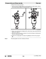
1. Install the bottom spring set
(g)
into the spring cylinder.
2. Place a new gasket
(f)
onto the spring cylinder.
3. Align the three holes in the spring box tool
(a)
with the three holes in the spring
system cover
(e)
.
4. Insert the three spring box screws
(c)
through the selected holes in the spring
box tool and through the holes in the spring system cover.
5. Turn the spring box screws
(c)
into the spring cylinder until they bottom out.
6. Turn the threaded rod
(d)
until the spring system cover makes contact with the
spring cylinder.
7. Apply Loctite® 243 to all the screws used to fasten the spring system cover to
the spring cylinder.
8. Install the screws
(b)
that hold the spring system cover to the spring cylinder.
Torque the screws to 24 Nm (18 ft.lbs.).
This procedure continues on the next page.
wc_gr012887
d
d
b
e
c
g
c
a
e
f
Summary of Contents for BS 50-4s, BS 50-4As
Page 1: ...Repair Manual Vibratory Rammer 5100018465 01 1015 5 1 0 0 0 1 8 4 6 5 EN...
Page 6: ...wc_tx004061gb_FM10 fm 6 Rammer Foreword...
Page 10: ...Table of Contents Rammer wc_br5100018465_FM10TOC fm 10...
Page 180: ...wc_td000553gb_FM10 fm 180 Rammer Technical Data Notes...
Page 192: ......
Page 193: ......

