wc_tx004029gb_FM10.fm
150
Rammer
Disassembly and Reassembly
Continued from the previous page.
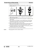
3. Center the lower spring set
(c)
and the spring system cover
(b)
under the
hydraulic press ram.
4. Align the holes in the spring system cover
(b)
as close as possible with the
holes in the spring cylinder.
5. Compress the lower spring set
(c)
until the spring system cover
(b)
rests on the
spring cylinder.
6. Apply Loctite® 243 and install the two screws
(a)
that hold the spring system
cover
(b)
to the spring cylinder. Torque the two screws to 24 Nm (18 ft.lbs.).
7. Remove the three M8 x 206 mm guide screws
(x)
.
8. Apply Loctite 243 and install the remaining screws that hold the spring system
cover
(b)
to the spring cylinder. Torque the screws to 24 Nm (18 ft.lbs.).
9. Re-install the ramming shoe. See topic
Installing the Ramming Shoe—BS50,
or
Installing the Ramming Shoe—BS60 and BS70
.
10.Re-install the bellows. See topic
Installing the Bellows
.
Results
The spring system cover has now been installed.
wc_gr012852
a
a
b
c
x
Summary of Contents for BS 50-4s, BS 50-4As
Page 1: ...Repair Manual Vibratory Rammer 5100018465 01 1015 5 1 0 0 0 1 8 4 6 5 EN...
Page 6: ...wc_tx004061gb_FM10 fm 6 Rammer Foreword...
Page 10: ...Table of Contents Rammer wc_br5100018465_FM10TOC fm 10...
Page 180: ...wc_td000553gb_FM10 fm 180 Rammer Technical Data Notes...
Page 192: ......
Page 193: ......


